MrDelsic
0
- Joined
- Oct 8, 2012
- Messages
- 40
- Points
- 0
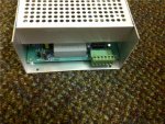
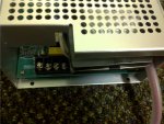
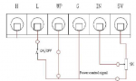
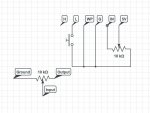
The power supply just got here!  Excited to test out the tube but I don't know the pinout and it didn't come with a manual. Pictures of the front and back are attached, I sent a email to LightObject asking for a diagram erlier this evning, but encase they don't get back to me soon- do any of you guys have an idea of the pinout, or how this power supply is adjustable?
Excited to test out the tube but I don't know the pinout and it didn't come with a manual. Pictures of the front and back are attached, I sent a email to LightObject asking for a diagram erlier this evning, but encase they don't get back to me soon- do any of you guys have an idea of the pinout, or how this power supply is adjustable?