

I've been mucking around with LED's for quite a while and using LM317T regulators, recently i have been playing around with PCB etching and thought i'd try my hand at making a small driver that is stable, or at worst, will drop off voltage as the batteries die. The flexdrives are great, but the 'feature' of increasing the output as the batteries die just makes me think of blowing diodes if batteries aren't kept in top charged form or regularly replaced.
SO,
This is not a tutorial or such, just a little post to show what can be done with some simple parts and a little bit of time. I'm sure that some of the real electronics gurus will be able to justify/explain the need for all the filtering, polity protection circuits and stuff that the other great drivers have but for me, i just wanted something with no frills to fit inside a pocket pal sized host.
The basic board is just 1oz copper single sided, its a fairly thick FR4 construction so i'm hoping to find some thinner PCB at some stage to reduce the height.
I used ' ExpressPCB ' to design the board and custom made the pads for the SMD trimmer (not pictured, still on order). This is a free program that can be used to order boards directly, or as i have used it, to design and print. Its main limitation is no gerber output, but it works fine for me and is very easy to use (also can link to schematics if required for larger projects).
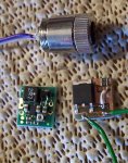
The pad for the LM317MDT voltage reg (in constant current mode) which will supply up to 500ma, was a standard package in the program already so i didn't need to create it specially.
I have it layed out so i can use 2x 0805 resistors (as pictured), or a single higher rated 1206 package SMD resistor. Using the jump wire (as pictured) the driver is set at a fixed value, in this case 2x 24ohms in parallel = 12 ohms = ~103ma (measured) draw. With an SMD pot in place where the white wire is the adjustment is quite good and you use the resistors to set the "max" allowed current so there can be no "mistakes" with turning a pot too far and having it jump in power and kill a diode.
As mentioned in the subject, this is a very simple, very basic driver whose design has served me well so far during testing and (although less sensitive) i've used similar design on LEDS for a long time with no issues.
It does not have input polarity protection, it does not have output polarity protection, or a cap (which i'm hoping to add without going double sided, or maybe just directly onto the diode, not sure yet). Some will notice there is actually no ground connection on this board at all. The soldering was done with solder paste and a heat gun for the SMD parts.
Like any linear regulator, it requires more volts in than a boost driver like the flexdrive and when the input voltage is well above the required minimum, the driver sheds it as heat, which can be an issue with such little copper available, but so far its OK for short periods up to around 5 minutes with 12V input it doesn't get crazy hot which is longer than i can imagine having a laser on.
Hope this gives people some ides for their own projects that keep things simple and adds that little extra edge of being customised and DIY.
SO,
This is not a tutorial or such, just a little post to show what can be done with some simple parts and a little bit of time. I'm sure that some of the real electronics gurus will be able to justify/explain the need for all the filtering, polity protection circuits and stuff that the other great drivers have but for me, i just wanted something with no frills to fit inside a pocket pal sized host.
The basic board is just 1oz copper single sided, its a fairly thick FR4 construction so i'm hoping to find some thinner PCB at some stage to reduce the height.
I used ' ExpressPCB ' to design the board and custom made the pads for the SMD trimmer (not pictured, still on order). This is a free program that can be used to order boards directly, or as i have used it, to design and print. Its main limitation is no gerber output, but it works fine for me and is very easy to use (also can link to schematics if required for larger projects).
The pad for the LM317MDT voltage reg (in constant current mode) which will supply up to 500ma, was a standard package in the program already so i didn't need to create it specially.
I have it layed out so i can use 2x 0805 resistors (as pictured), or a single higher rated 1206 package SMD resistor. Using the jump wire (as pictured) the driver is set at a fixed value, in this case 2x 24ohms in parallel = 12 ohms = ~103ma (measured) draw. With an SMD pot in place where the white wire is the adjustment is quite good and you use the resistors to set the "max" allowed current so there can be no "mistakes" with turning a pot too far and having it jump in power and kill a diode.
As mentioned in the subject, this is a very simple, very basic driver whose design has served me well so far during testing and (although less sensitive) i've used similar design on LEDS for a long time with no issues.
It does not have input polarity protection, it does not have output polarity protection, or a cap (which i'm hoping to add without going double sided, or maybe just directly onto the diode, not sure yet). Some will notice there is actually no ground connection on this board at all. The soldering was done with solder paste and a heat gun for the SMD parts.
Like any linear regulator, it requires more volts in than a boost driver like the flexdrive and when the input voltage is well above the required minimum, the driver sheds it as heat, which can be an issue with such little copper available, but so far its OK for short periods up to around 5 minutes with 12V input it doesn't get crazy hot which is longer than i can imagine having a laser on.
Hope this gives people some ides for their own projects that keep things simple and adds that little extra edge of being customised and DIY.


")