I need to complete a Science fair project. Quite simply, I have purchased three lasers pointers, two of which seem to be the same model. Although, the nature of my project requires me to modify these lasers so that I may burn items with them. I know that "pot" mods may reduce the life of the diode, yet that is quite redundant seeing that I only would need the lasers to function for an approximate minute. Although as I will mention below, I would discover that my laser pointers (or at least the two similar pointers) do not have a potentiometer, yet I mean to state that I am open to options that may slightly lessen the laser pointers life. I have seen videos of soldering components to achieve a greater wattage, yet obviously the circuitry in my laser pointers will be labeled and configured differently from the models in the video. I have purchased all of the laser pointers from "Amazon.com", and will provide the URL's below. That being said, merely "googling" the Item Model Number and ASIN given on the technical details won't bring anything useful up.Amazon.com: American Science & Surplus Red Laser Pointer With Case and Batteries: Electronics
Amazon.com: 5mw 532nm Astronomy Powerful Green Laser Pointer - Black: Electronics
Amazon.com: 5mw High Quality Violet Purple Blue Ray Laser Pointer Pen: Electronics
I understand that these are extraordinarily cheap laser pointers. I understand that it is ridiculous to attempt to modify these to dramatically destructive power. I only hoped to push the power enough to scorch some egg whites.
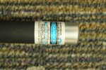
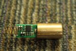
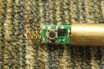
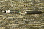
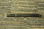
I had spent probably what had been too much time trying to figure out how to disassemble one in the first place. Videos would spend 5 minutes describing how to get the tip of the pointer off (which I had figured out myself anyway) and then seemed to completely ignore the procedure for removing all the innards. I eventually (and begrudgingly) took a powered precision hand saw and ran it up the case, which is where I have peeled it and took out the diode. So, this circuit dose not have a potentiometer, which may have made this just so much easier, and I am unsure of what components to touch.So how can I modify these?