Dr_Evil
0
- Joined
- Feb 25, 2008
- Messages
- 2,128
- Points
- 63
I'd like to verify this to make sure I'm correct in my thinking.
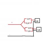
Let's say I have two 1.9 ohm resisters in parallel. The actual resistance would be .95. The multimeter should read .95, right? I get ~2.4 ohms across one pair and about 1.8 across the other. See the diagram below to understand.
The 660 in my projector wasn't working. Turns out both diodes went LED so I replaced them. The output still wasn't anywhere near what it should be. The driver is a Lasever LSR-PS-I. I cna't get the output to go over ~350mA. The voltage is ~3.99 with the laser on. The driver is supposed to put out up to 2A though.
The driver Lasever Inc.-LSR-PS-I
This is the way it was set up when I bought this projector so don't blame me. lol


