TSJim
New member
- Joined
- Oct 16, 2020
- Messages
- 1
- Points
- 1
Hello!
I have a technical repair issue that I hope this community can help me with.
A fairly powerful green laser pointer was donated to our shop recently by a client.
The client said it was previously working, and highly visible in daylight. He used it to effectively scare crows from the large trees in his backyard.
According to the client, the unit was becoming intermittent, so he opened it and thought that the driver board was shorting against the inside of the case. He attempted to sand down the edges of the PCB to prevent the suspected shorting, but he said that the laser stopped working after that.
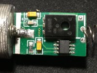
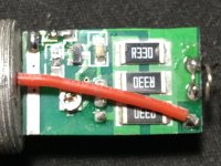
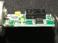
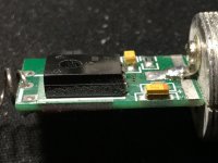
Upon inspection, it is apparent that he sanded the PCB too far and took off traces on the sides of the PCB.
Here are some photos of the PCB, and you can see that the traces on the sides of the PCB have been sanded away:
I have done a fairly extensive Google image search for this particular diver board, but I'm not seeing anything similar.
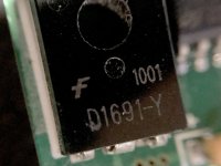
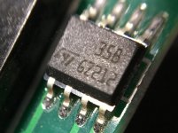
The transistor or MOSFET part number is" D1691-Y", and the comparator IC part number is an ST 35B GZ212. Here are pics of these components:
Does anyone here have this same driver board in their laser that they could post photos of, or have info on the PCB traces or a schematic? I would appreciate any technical info on this driver board so I can restore the sanded-off traces to get this unit working again.
Thank you!
--
TSJim
I have a technical repair issue that I hope this community can help me with.
A fairly powerful green laser pointer was donated to our shop recently by a client.
The client said it was previously working, and highly visible in daylight. He used it to effectively scare crows from the large trees in his backyard.
According to the client, the unit was becoming intermittent, so he opened it and thought that the driver board was shorting against the inside of the case. He attempted to sand down the edges of the PCB to prevent the suspected shorting, but he said that the laser stopped working after that.
Upon inspection, it is apparent that he sanded the PCB too far and took off traces on the sides of the PCB.
Here are some photos of the PCB, and you can see that the traces on the sides of the PCB have been sanded away:


I have done a fairly extensive Google image search for this particular diver board, but I'm not seeing anything similar.
The transistor or MOSFET part number is" D1691-Y", and the comparator IC part number is an ST 35B GZ212. Here are pics of these components:


Does anyone here have this same driver board in their laser that they could post photos of, or have info on the PCB traces or a schematic? I would appreciate any technical info on this driver board so I can restore the sanded-off traces to get this unit working again.
Thank you!
--
TSJim


