Welcome to Laser Pointer Forums - discuss green laser pointers, blue laser pointers, and all types of lasers

LPF Donation via Stripe | LPF Donation - Other Methods

Links below open in new window

ArcticMyst Security by Avery

Question about amc7135 and 445nm LD..

SHIN

0
Joined
Jul 25, 2009
Messages
207
Points
18
Hi.

I built a few of 445nm with v5, microboost.
But maximum current of v5 to 445nm is 1.2A and microboost is 1.1A.
So I am looking for high current driver.

I have my custom P60 heatsink already, so I can use round circuit board for LED.
http://laserpointerforums.com/f44/drop-laser-module-p60-44687.html

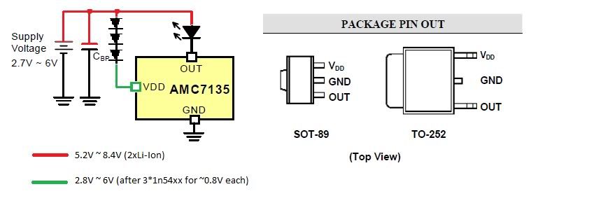
Dealextreme's cheap 4x amc7135 driver can supply 1.4A, and 5x can 1.75A.
Input voltage of amc7135 ranges upto 6V-7V.
Vf of 445nm LD is over 4.2V.
And drop-out voltage of 1N54xx diode(3A) is 0.8V-0.9V.

I have question:
Can I build 1.4A/1.75A 445nm
with 4x/5x amc7135 driver
and 2 of serial Li-ion battery(8.4V)
and 3 of 1N54xx(ca. 2.5V drop) for voltage drop of batteries ??

I hope this will be possible.. Any comment welcome...:bowdown:

SHIN
 

Attachments

  • 1N5400.pdf
    140 KB · Views: 164
  • amc7135.pdf
    181.6 KB · Views: 862
Last edited:


Joined
Dec 29, 2009
Messages
3,136
Points
63
Try it out with a test load. A PoIV graph is now available in the 445 forum http://laserpointerforums.com/f65/3x-445nm-ld-piv-plot-53927.html

I don't see why it shouldn't work, but it can't hurt to test. I'm sure you have a few unknown bin Cree LEDs you could test with... I think I understand what you plan on doing: put a few diodes on the Vcc pin to drop the voltage to the chips w/o dropping the voltage to the LD. That's a pretty common hack for running multiple LED emitters off of a 7135, using LEDs instead of normal ones.
Poorman Mutli-Lux setup method - CandlePowerForums

The main modification would be that you probably only want to drop the Vcc but not the LD's Vin, so you would add the diodes between Vin on the driver board and the paralleled Vcc pins on the 7135, where in Download's example the extra diodes (LEDs) are dropping volts from the Vcc and from the third LED's supply.

BTW, I'm having a P60 heatsink made for my L2, pretty excited. I was just curious if you had any surefires and if the sinks you made for your L2 fit your surefire?
 

SHIN

0
Joined
Jul 25, 2009
Messages
207
Points
18
Hi. BShanahan14rulz.

Thank you.;)

I'll try like this:

445nmLD===7135driver---1n54xx-1n54xx-1n54xx-----Li-ion--Li-ion-----tail switch
<---------------- P60 module -------------------> <---battery--->

My P60 heatsinks were made after surefire-compatible P60. (nailbender@CPF, dealextreme etc)
Each and every diameter and length was measured.
I have surefire L4, E1L and non-surefire P60 hosts but no surefire P60 host.
I think those will fit any P60-compatible host including surefire.

SHIN
 
Joined
Dec 29, 2009
Messages
3,136
Points
63
Just to clarify, this is what I was thinking:
shin7135445.jpg


But with a test load and not a real laser diode. I took the Vf of the 1n5400 diodes from the datasheet graph, assuming ~1A. At 2A it's about 0.85V.

I don't know if the regulator needs to compare the Vin to the V after the LED, it shouldn't have to. If it does, though, I bet it would cause some annoying malfunctions.

Anyways, give it a shot with a test load, the load should drop about 4.5-4.6V if you want to be precise. throw in a very low resistance high power resistor to measure the current, etc. etc., you know the story.
 

SHIN

0
Joined
Jul 25, 2009
Messages
207
Points
18
Thank you for the diagram. BShanahan14rulz.

I tested with my custom 2A/3A test load and it seemed to work fine.
445nm LDs are on its way.
I'll post the picture if this is successful.

Again I appreciate you.

SHIN
 

gillza

0
Joined
Jul 26, 2010
Messages
583
Points
28
Just to clarify, this is what I was thinking:
shin7135445.jpg


But with a test load and not a real laser diode. I took the Vf of the 1n5400 diodes from the datasheet graph, assuming ~1A. At 2A it's about 0.85V.

I don't know if the regulator needs to compare the Vin to the V after the LED, it shouldn't have to. If it does, though, I bet it would cause some annoying malfunctions.

Anyways, give it a shot with a test load, the load should drop about 4.5-4.6V if you want to be precise. throw in a very low resistance high power resistor to measure the current, etc. etc., you know the story.

Please correct the nOOb if I'm wrong as I'm trying to understand how AMC7135 functions: from what I read I gather that the purpose of the Vdd is to measure the potential at that point (at Vdd) and to adjust potential at OUT in such a way that the Voltage drop across the diode will be the Vf of the diode? And in this case the voltage dropped only at Vdd to meet the chip's maximum Operating voltage while keeping it high at Diode's positive terminal so that there will be "room" for Voltage drop?
 
Last edited:
Joined
Dec 29, 2009
Messages
3,136
Points
63
Please correct the nOOb if I'm wrong as I'm trying to understand how AMC7135 functions: from what I read I gather that the purpose of the Vdd is to measure the potential at that point (at Vdd) and to adjust potential at OUT in such a way that the Voltage drop across the diode will be the Vf of the diode? And in this case the voltage dropped only at Vdd to meet the chip's maximum Operating voltage while keeping it high at Diode's positive terminal so that there will be "room" for Voltage drop?


You may be onto something here. Perhaps this would only be usable if the AMC7135 are well heatsinked or the diodes also drop the voltage to the LD, I.E. the diodes trop the main supply voltage. It looks like the AMC senses the voltage before the load and tries to compensate how much V it drops to keep the current near 350mA. I guess when I have some time I ought to do some testing, now that I have more AMC's. It only seems to take a reference on the Vcc pin, according to the datasheet, though. Not sure why.
 
Last edited:

gillza

0
Joined
Jul 26, 2010
Messages
583
Points
28
You may be onto something here. Perhaps this would only be usable if the AMC7135 are well heatsinked or the diodes also drop the voltage to the LD, I.E. the diodes trop the main supply voltage. It looks like the AMC senses the voltage before the load and tries to compensate how much V it drops to keep the current near 350mA. I guess when I have some time I ought to do some testing, now that I have more AMC's. It only seems to take a reference on the Vcc pin, according to the datasheet, though. Not sure why.


Vcc is Vdd? I guess it makes sense assuming that amc7135 measures the potential difference at Vdd relative to GND, and adjusts potential at OUT (again relative to GND) so that the voltage drop across the diode is its Vf (forward voltage) necessary to maintain 350mA output.

Unless I'm completely talking out of my A$$ here the LD diode functions more or less like a one way resistor, so following the Ohms law, assuming that LD's resistance is constant, in order to push certain current through it voltage accross the LD needs to be changed (to maintain Ohms law), and that is what AMC7135 does.

Now keep in mind I'm in no way electrical engineer, my background is in chemistry and biochemistry, so I may be completely wrong!!! I'm here to try to understand it :)
 
Joined
Dec 29, 2009
Messages
3,136
Points
63
[evil voice] I think you might be asking questions that are better left alone

But on a more serious note, I'm not exactly sure of the voodoo that goes on inside the chip, and the datasheets are very very generic. I AM thinking that it senses the voltage on the OUT pin as well, even though it's not indicated in the logic diagram on the datasheets, because on the newer versions it's recommended to add an output capacitor to ground if the length of the wire between the OUT pin and the load is longer than 3cm, or on a different board. Usually, these short length requirements are indicative of some sensitive comparator thingamabobs in there.

So I can say that what you think sounds more or less like what's going on, but I can't reply back to you for certain that that is what it is doing. If you are really curious, I might suggestyou ask at CPF if anybody knows how exactly they work. All I know is that it sinks 350mA through the out pin, and if Vf+.15V>Vbatt, then it pretty much direct-drives it with no current limiting (which wouldn't matter because your current wouldn't go higher than .35 anyways at that low supply voltage)
 

gillza

0
Joined
Jul 26, 2010
Messages
583
Points
28
.....All I know is that it sinks 350mA through the out pin, and if Vf+.15V>Vbatt, then it pretty much direct-drives it with no current limiting (which wouldn't matter because your current wouldn't go higher than .35 anyways at that low supply voltage)

Um so 0.15V is the dropout voltage of AMC7135?
 
Joined
Dec 29, 2009
Messages
3,136
Points
63
yep. As long as your LD/LED Vf+0.12V is less than the supply voltage, (and the supply voltage to the Vdd pin is within spec) the current will be regulated. It is more efficient the closer your battery voltage is to Vf+0.12V. Some people say it works ok when out of spec, as long as you heatsink them well.
 

gillza

0
Joined
Jul 26, 2010
Messages
583
Points
28
Got it :) Thank you. This thread did shed some light on me and you Sir explained things splendidly :) Much appreciated!


Top