- Joined
- Sep 22, 2010
- Messages
- 1,360
- Points
- 48
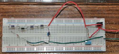
I have a quick question for you guys. I decided to build the DIY driver from Laser driver - It can be done as a way to get some experience. I built it according to the diagram and when I tested it after a slight tweaking of the pot it was putting out a steady 250mA. When I tested the output voltage it was at 5.1v which would fry my diode. Then I built my dummy load using the 4 diodes and followed by a 1ohm resister. When I measured across the resistor I was only getting .44v at 130mA which seems way wrong. I built it on a breadboard in case something like this happened and I need to rebuild it. Here's a picture of the driver plus test load. There is a jumper pin connecting the two pins on the pot like in the diagram that is hidden under the ground wire in the pic.

The full sized version can be found on my flickr page.
All sizes | driver | Flickr - Photo Sharing!
My power supply for the test was 4 fully charged eneloop AAs which were putting out about 5.3-5.4v total.

The full sized version can be found on my flickr page.
All sizes | driver | Flickr - Photo Sharing!
My power supply for the test was 4 fully charged eneloop AAs which were putting out about 5.3-5.4v total.


