Welcome to Laser Pointer Forums - discuss green laser pointers, blue laser pointers, and all types of lasers

LPF Donation via Stripe | LPF Donation - Other Methods

Links below open in new window

ArcticMyst Security by Avery

Newbie here. NI Multisim green laser diode help?

Joined
Jan 16, 2013
Messages
34
Points
0
I just registered minutes ago since i really like lasers (despite of few knowledge) and so i want to learn laser stuffs more; and i hope im not in a wrong section.

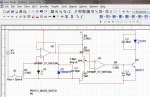
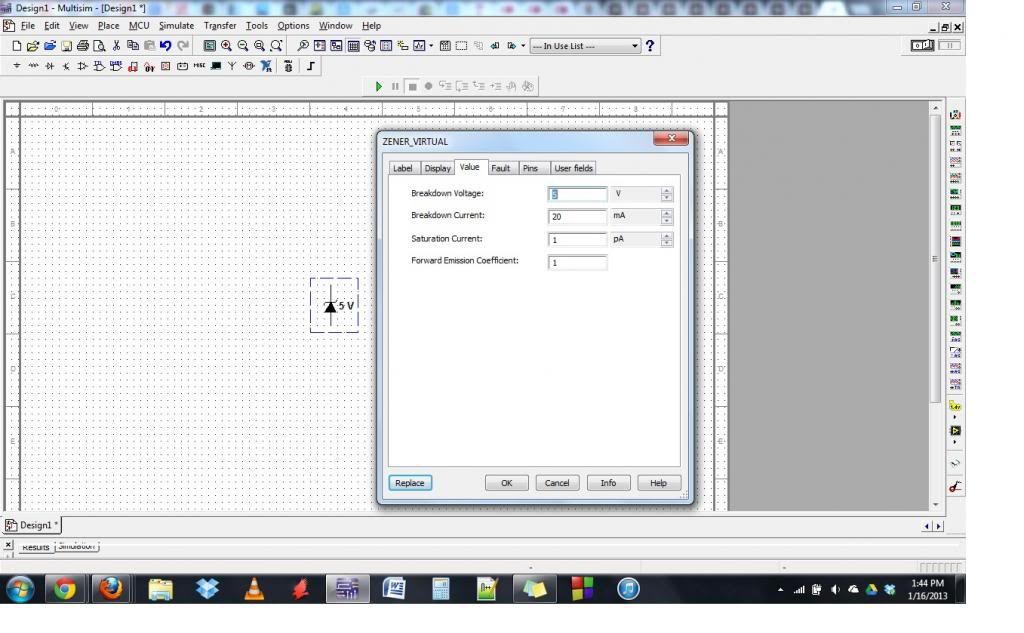
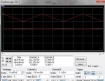
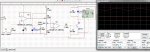
So anyways, i have this project i'm working on about green laser diode. I copied a schematic here in Sam's laser. I found this pic. (glpdrv4.gif) on the site. then so i copied (without any knowledge on laser diode drivers and stuff) and put it on multimeter no reading. (I know it's stupid of me not to know these stuff.) Can you guys help me out tell me what's wrong with my copied schematics?(laserdiode.jpg) I have to put it on test and attach some oscilloscope to see the waves and stuff and also a wattmeter but unfortunately doesnt work.

And please teach me how to connect the driver to an oscilloscope thanks

Thanks for all the help
 

Attachments

  • glpdrv4.gif
    glpdrv4.gif
    5.6 KB · Views: 8,078
  • laserdiode.jpg
    laserdiode.jpg
    226.4 KB · Views: 11,196


Joined
Feb 1, 2008
Messages
2,894
Points
0
Ermm... so you're actually trying to drive an 808nm IR diode to pump the optics to get green out. We've got that straight, right?

Sam has some nice schematics, but for what we normally use lasers for here, there is rarely a need for so many parts. There are simpler LM317 based drivers otherwise available. Very simple.


But.. if you must use this other circuit. Make sure your multisim parts are correct. Is your zener at 1.25V? Is your LD set with a Vf at ~ 1.2V? Do you know what Hfe the source transistor is supposed to be?

In Multisim, you may have to set some initial conditions IE charge voltage on capacitors and state of the op amp output pins. Just some ideas. But really, I suggest googling the LPF thread about the LM317 driver. Its about 3-4 parts.
 
Joined
Jan 16, 2013
Messages
34
Points
0
i tried to look some specific materials in multisim so i just put something random that might replace the parts.
But.. if you must use this other circuit. Make sure your multisim parts are correct. Is your zener at 1.25V? Is your LD set with a Vf at ~ 1.2V? Do you know what Hfe the source transistor is supposed to be?
I'm no really an expert in lasers so I wouldn't know. Please lend me knowledge and correct or suggest replacements for my schematic for it to work. I know it's kind of irritating tho can you please elaborate the explanation for these? I just need a working green laser diode of about 100mW-150mW and I'm good to go.
 
Joined
Feb 1, 2008
Messages
2,894
Points
0
In Multisim, you can edit a component if it is a "virtual" component. So, instead of picking a specific zener diode, pick "virtual zener" from the component menu. After placing that component, you can right-click on the component, and hit "properties". Go to the value tab, and you can edit your component's parameters to what the schematic needs.

multi_zps8c80d9a1.jpg


But I'll go ahead and point you here: Try this circuit. You can buy all the parts at a local radioshack (are you in the US?). http://laserpointerforums.com/f42/diy-homemade-laser-diode-driver-26339.html

That thread will tell you everything you need to know about the circuit, and about driving a diode etc.

Do you actually have a green laser diode? Or a green laser module?
 
Last edited:
Joined
Jan 16, 2013
Messages
34
Points
0
That thread will tell you everything you need to know about the circuit, and about driving a diode etc.

Do you actually have a green laser diode? Or a green laser module?

Thanks, no im not from US so we don't have Radioshack unfortunately but we some shops here that may have stuffs that I need. Would you mind answering my one question : if I finish the circuit, how do I know that it works? (NI multisim) should I put a wattmeter or multimeter but i dont know where to put them.
 
Joined
Jan 16, 2013
Messages
34
Points
0
I think I had the circuit working since I can now use multimeter but I've got varying results and it is ugly. and my wattmeter reading is zero and the oscilloscope waves are complete messed up. (first a square wave now a triangular wave) i attached an image of what oscilloscope showed. a triangular wave.
 

Attachments

  • osc.jpg
    osc.jpg
    87.7 KB · Views: 778
Last edited:
Joined
Sep 20, 2008
Messages
17,622
Points
113
You are new here so I'll explain some simple Forum
etiquette...:beer:
It is very easy to edit or add to a post by using the
[Edit] button at the bottom of your posts.
Using that button would negate the possibility of you
getting Negative Reps for Triple Posting when it is
not necessary......

BTW opening the same Thread in different sections
of the Forum is called Spamming and it may also
get you some of those unwanted Neg Reps....

On a 3rd note it would easy to know where you are
from if you would add your location to your Profile.


Jerry

You can contact us at any time on our Website: J.BAUER Electronics
 
Last edited:
Joined
Feb 1, 2008
Messages
2,894
Points
0
Thanks, no im not from US so we don't have Radioshack unfortunately but we some shops here that may have stuffs that I need. Would you mind answering my one question : if I finish the circuit, how do I know that it works? (NI multisim) should I put a wattmeter or multimeter but i dont know where to put them.

You must take your multimeter and connect it in series with the laser diode. You should be able to set your multimeter to "current" reading mode or "A". If the current reading you get is the current you desired, the circuit is operating properly. Be sure to read the stickies and do some more searching. All the info you need is here on the forum. :beer:
 
Joined
Jan 16, 2013
Messages
34
Points
0
You must take your multimeter and connect it in series with the laser diode. You should be able to set your multimeter to "current" reading mode or "A". If the current reading you get is the current you desired, the circuit is operating properly. Be sure to read the stickies and do some more searching. All the info you need is here on the forum.
Thanks, yeah i got it operating now. the multimeter, well except with the wattmeter. the problem about the multimeter is that the ammeter reading varies magnitude and so as the voltage reading. it changes like when I stop simulating and simulate again gives a different reading like from 21V to 3mV when my input voltage is only 3V! that's just ugly. you have some suggestions to resolve, i really got nothing for im only new also in ni multisim.
 
Joined
Feb 1, 2008
Messages
2,894
Points
0
You're simulating the lm317 now right? Both circuits will need a higher input voltage to slip into regulation. Post pictures of where you are making measurements.
 
Joined
Jan 16, 2013
Messages
34
Points
0
after i replaced the zener i still simulate the same circuit. Where do I put the LM317(H)? in sam's schematic i copied i cant see a voltage regulator there. attached is the lm317 I found (on internet but i also have one in master database).
And as Ive said the circuit multimeter reading has ugly variations it changes. here's a pic. Still no improvement. :(
I's kind of funny stupid of me to connect the oscilloscope in random (and asking bunch of stupid questions sorry). please help me out.

Im no experimental type so im having trouble where to point out the problem multisim is also a bit new to me.

wattmeter reading in (current and voltage) is zero.
multimeter changes.
 

Attachments

  • raf.jpg
    raf.jpg
    105.5 KB · Views: 3,252
  • LM317 Regulator.zip
    34.1 KB · Views: 52
Last edited:


Top