Welcome to Laser Pointer Forums - discuss green laser pointers, blue laser pointers, and all types of lasers

Buy Site Supporter Role (remove some ads) | LPF Donations

Links below open in new window

FrozenGate by Avery

Eagle questions

Joined
Dec 27, 2011
Messages
2,062
Points
48
I am trying to use Eagle to design a new test load. I figure a test-load is a pretty basic starting point and I want to see if I can build a better mousetrap.

Regardless of whether it is something I can sell here, or just something for my own use, I'd like to do this to learn more about building a circuit and designing a PCB.

I've done a few tutorials and I'm still not 100% sure when I should use a bus or a wire and some other details, but I can design a schematic for the most part.

Where I'm really running into problems is the parts library.

For example, I want to use a TO-220 package resistor for my 1 ohm resistor so that I can get a high wattage resistor with a heat sink on it.

I can't find a simple TO-220 package resistor in Eagle.

I want to add some bigger posts and terminal solutions for connecting wires. I don't see where to find that. I want to use TO-220 diodes for the same reasons above.

Is Eagle the best way to go with this? Or am I just not learning enough about Eagle yet?

In short, should I be using Eagle? Is there something better?

If so, is there an easy way to get TO-220 resistors and other packages into the program?

Does anyone know of any good tutorials or example pages on Eagle?

I appreciate any tips or pointers or ideas.


Eagle has a lot of parts in the built in libraries, but you still wont find most exotic parts already there. You can download more libraries from the internet but still don't expect to find everything you want to use pre-made.

You need to make you own library to put all your parts in. When you open your new library it will be a blank window. At the top find the three buttons Device, Package, and Symbol. To make a new part you need to use the package and symbol buttons to draw the schematic symbol and the board footprint. Once you have both of those you use the device button to link them together.

I'll walk you through creating an eagle part for this 1 ohm resistor: PF2203-1RF1 Riedon | PF2203-1.000-ND | DigiKey

1. From the home screen, create new library with file>new
2. Save and name the library
3. Click the package button, type "TO220-2" in the new: box and hit OK
4. Look for package measurements in the datasheet, usually at the very bottom.
5. Figure out a good grid scale. For a big and less complex part like this I would just stick with the default 0.05" with 0.025" alt. (this allows you to get a higher accuracy by holding alt) For tiny parts with lots of pins I usually do a metric grid of 0.5 and 0.1 alt. They are usually made with metric measurements. Ideally the grid should let you easily place all the pads/holes without to much work.
6. Figure out the hole size you want to use. I would say 0.05" or 0.04" so you have some room but its also small enough that it will hold it at the point where the leads get thicker (.06").
7. On the left side click the green "pad" button.
8. Type in 0.04 (or 1mm if you are working in metric) in the drill size at the top and hit enter.
9. Chose pad shape. I'd go with either the round or oval one.
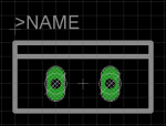
10. Lead spacing is 0.2" and the grid is 0.05" so place one hole two notches to the left of the center mark, place the other two notches to the right. If you used the oval shape make sure you have them aligned vertically. Right click rotates.
11. If you want you can make an outline with line/wire tool using the tPlace layer (change this in top left) using the dimensions of the part from the datasheet. Use something like 0.01 or 0.016 for the line size. I also added an extra line on the back to show the tab side.
11. Type "text" and hit enter. In the box that pops up type ">NAME" and press OK. Change layer to tNames in the top left. Chose a size you think is appropriate. I usually go for 0.032, 0.024 is pretty much the smallest you can go and still be kinda readable from the laen/oshpark boards. Place the text a couple notches above the pads. (This parts tells eagle where to put whatever name you have given the part, like R1 for example)
12. If you want type "name" then click on each of the pads to give them a name. There is no point to do so on this part since its just a resistor, but anything polarized or with more than 2 pins its a good idea to to this.

You should have something like this:
attachment.php


13. Save, close library.
14. Got to a premade library that has resistors. I like rcl. Open that library and click the symbol button, find the standard resistor symbol and open it. Verify that this is a regular old resistor symbol. It is called "R-US" in the rcl library.
15. Grab the select/group tool on the left and highlight it, text and all.
16. Type "copy" hit enter
17. Hold control key and right click the symbol. You should be able to move around a copy of the entire thing now.
18. Close the window
19. Open your library, make new symbol called RESISTOR.
20. File>paste and place the symbol
21. Save.
(If you are making something else that there isn't a pre made symbol for you just draw it yourself, its not hard)
22. Click device, make new called something like TO220-RESISTOR
23. On the left side click the add part button and grab the resistor symbol, put it right on top of the center mark in the white space.
24. On the right side click new and find your to-220-2 package.
25. On the right click connect, this little pop up box lets you connect the schematic pin to the package pins. (this is why naming is important if you have more complex parts)
26. Click connect twice then OK
27. Save, close library.
DONE! Now make your other parts and schematic.
 

Attachments

  • to220-2.PNG
    to220-2.PNG
    6.7 KB · Views: 975


Back
Top