Welcome to Laser Pointer Forums - discuss green laser pointers, blue laser pointers, and all types of lasers

LPF Donation via Stripe | LPF Donation - Other Methods

Links below open in new window

ArcticMyst Security by Avery

diode laser driver

Joined
Dec 27, 2008
Messages
38
Points
0
I have never found a data sheet for the PHR's diode... would be good to get one  ;)

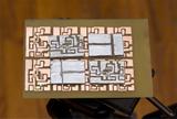
I've done a test board for this driver, in a couple of days I should complete it getting all the parts needed.
Despite the really small size of this board, toner transfer paper worked very well. I have built it on a double layer circuit, using the bottom layer to solder the power supply wires and a small imput capacitor.

some pics:


on the last photos there's a 100nF capacitor (standard 5mm lead distance) as size comparison.


Joined
Dec 27, 2008
Messages
38
Points
0
I've built two version of this driver, one based on the simple schematic, another one based on this schematic, but without good results. In the second schematic I've replaced the MAX480 with any single supply opamp I had laying there, tried TL082, LM358N, NE5532, OPA2228 without getting any regulation. Since I've used dual opamps, I've tried both to leave the second OP connections free or setting it to a voltage follower pointed to 0V.

The mosfet is allways being driven at full +V voltage by the opamp, saturating it and getting all the available current into it, I have been measuring 3 amps off a single AA cell. Can anyone tell me what I've done wrong? traces on the pcb have made using eagle following the schematic both of the first and the second driver, and then double checked before building the circuit, so the problem is not in the circuit board. Some photos and schematics about the second driver built yesterday:

First, the second schematic redrawn in eagle to produce directly the pcb.
http://i44.tinypic.com/2m6sw86.png

second, the pcb artwork drawn following the schematic posted up there.
http://i41.tinypic.com/2wd9gfb.png

and then some construction pics. The driver has been build on a double sided board, any track is perfectly insulated, no shorts have been found anywhere. Top layer is connected to gnd, all needing pins have got a large area of copper scraped off to avoid involontary groundings.


Can anyone please help me to figure out why both these circuits are saturating my mosfet and won't get in any way to regulate? I've tried anything. pulling up down the output with two 100k resistors connected to v+ and gnd, setting the second opamp as a voltage follower getting 0V imput to avoid oscillations, but nothing got my circuit into proper regulation.
 
Joined
Nov 24, 2007
Messages
65
Points
0
I'm no expert, to me it looks like R4 will be pulling the gate of the mosfet high all the time causing it to be switched on constantly. What happens if you remove R4?
 
Joined
Dec 27, 2008
Messages
38
Points
0
I've rebuilt the pcb using an OPA177 with a dual power supply, works well. I'll post pics soon. runs well for 0-5A, with some adjustments this may become a pretty good laser diode driver.


Top