Welcome to Laser Pointer Forums - discuss green laser pointers, blue laser pointers, and all types of lasers

Buy Site Supporter Role (remove some ads) | LPF Donations

Links below open in new window

FrozenGate by Avery

Deadal Circuit Information

Joined
Mar 15, 2009
Messages
74
Points
8
Hey, I was thinking of building a new PHR-803T Blu-Ray laser pointer, but I want to get it as long life as possible. I have a few questions.

1. Can the DDL Circuit (if equipped with a 1000-ohm variable resistor instead of a 100 ohm) maintain an out-put of 120mA?

2. What is the preferred mA and mV reading for a PHR-803T Blu-Ray laser diode?

3. Must I run the circuit through a dummy load before getting my reading or could I just use the positive and negative coming from the circuit?

4. What is the recommended run time for a laser diode before it can burn out from its own heat or some other cause?

Please help me out. I only built 2 lasers both of them being the PHR lasers, but both burnt out.


Hello and welcome.... I have built several lasers using DDL circuit. Here is some information for you pertaining to your questions...

1. You wont need a 1k ohm pot, but yes it would work as well.

2. The PHR-803T diode runs well at around 90-110 mA. This would give you roughly 80 to 100mW of power. You can push them higher but I would not recommend it for the life of the diode. At these powers you can easily pop a balloon or light matches.

3. You do not have to run a dummy load, although it is safer to do so. Also current is measured in series with a DMM. Meaning you must connect the leads of the DMM in series with your LD to measure current. There are ways out there to build your own dummy load with four 1N4001 diodes and a resistor.

4. As I said above about the current. Stay around 90-110 mA and you should have a long lasting diode. Also try to get good heat sinking. I recommend a host from JayRob. He machines his own heat sinks and from what I hear, they are excellent!

Finally, be patient with your build. Don't try and rush things along to quickly because that's when errors occur and diodes tend to die.
 
... Meaning you must connect the leads of the DMM in series with your LD to measure current...

What do you mean by this? I don't have too much familiarity with terms for circuits. I have learned this a while ago, but I forgot.
 
Just make a quick test load for your driver, for a blu-ray test load you get 4 14N001 diodes and solder them in a chain from your positive driver terminal, then in between the last 14N001 diode and your driver put in a 1ohm resistor, then measure in mV across the resistor and you will know how much current your driver is putting out, I recommend setting your driver to 110mA for a PHR-803T.

If you can't find a 1ohm resistor, put any relatively low ohm resistor in and use this equation:

current = voltage/resistor size
(I=V/R)

That way say you have a 2ohm resistor, you would measure the voltage across your resistor and say you get 200mV, divide that by 2 as your resistor is 2ohm, and you now know your driver is outputting 100mA :)

GL, hope this helps.
 
What do you mean by this? I don't have too much familiarity with terms for circuits. I have learned this a while ago, but I forgot.

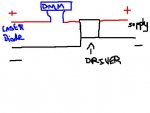
Okay take a look at this crude drawing....

Where it says DMM, this is where you connect your leads from your multimeter. Make sure the DMM is set to mA. If you're using DDL circuit, use a 10 ohm resistor and a 100 ohm potentiometer. Before you hook ANY power up, make sure your 100 ohm pot is at max resistance. As you dial the pot and the resistance goes down, the current(mA)will go up. If you have the DMM hooked up as I have shown you in the drawing, then your reading in mA will be shown on the DMM. I hope this makes sense to you and good luck.
 

Attachments

  • untitled.JPG
    untitled.JPG
    16.7 KB · Views: 312
Last edited:
Just make a quick test load for your driver, for a blu-ray test load you get 4 14N001 diodes and solder them in a chain from your positive driver terminal, then in between the last 14N001 diode and your driver put in a 1ohm resistor, then measure in mV across the resistor and you will know how much current your driver is putting out, I recommend setting your driver to 110mA for a PHR-803T.

If you can't find a 1ohm resistor, put any relatively low ohm resistor in and use this equation:

current = voltage/resistor size
(I=V/R)

That way say you have a 2ohm resistor, you would measure the voltage across your resistor and say you get 200mV, divide that by 2 as your resistor is 2ohm, and you now know your driver is outputting 100mA :)

GL, hope this helps.

Okay, I do have a 1-ohm resistor, but its big and bulky it blocks 1 watt of power, would that effect anything? (Note: I bought it from Radio Shack, the only 1-ohm resistor they have.)

If not, I have an extra 10-ohm resistor so i bet I could use that too. But the only problem is that I don't have a 1000 mA reading. Only mA-20 and mA200.

EDIT: Did you mean "...then measure in mV across the resistor..." or did you mean to put mA?
 
Last edited:
no please, not again. why are you guys still telling people to use dummy loads for linear drivers?

To measure the current your driver is set to just put the MM in amp mode as load!
 
why would I lie to you. Just do it, but again, make sure that you put your MM on amp mode and that you put the red wire on the right hole. If you have 2 holes, one for 200mA and the other for 10A, put it on the one with the higher value ;)
 
its actually a digital multimeter. I can set it to a max of 200mA and there is COM (negative) and ADC-VDC-(Degrees) F and another positive hole, VAC.


Back
Top