Welcome to Laser Pointer Forums - discuss green laser pointers, blue laser pointers, and all types of lasers

Buy Site Supporter Role (remove some ads) | LPF Donations

Links below open in new window

FrozenGate by Avery

Custom laser array driver

likevvii

Member
Joined
Mar 2, 2020
Messages
74
Points
18
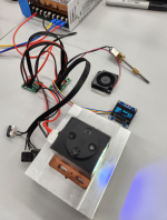
I have a module that has a built in laser array, optics, and phosphor.
The laser array is a nubm36. Basically a 240W array @3A.

I am searching on my own already, but I might as well ask here:

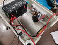
Do you guys have a recommendation for someone capable of producing a custom driver that is more compact than the one I have in the picture?
I want a wider input voltage range so I can use a li-ion battery pack.
I am looking for something that is similar to this in size:
https://www.maimanelectronics.com/product-page/high-power-laser-diode-driver-oem-cw-15а-40v-sf6060

I want the unit cost to be under 100USD so it can be a consumer product.

Do you think 3500usd is enough to develop a driver?

Thanks.

I'm also trying to customize an aspherical fresnel lens, 165mm diameter, 120mm focal length, AR coated.

uc

uc


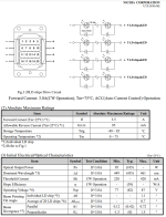
nubm36.png
1676799175736.png


These work stably. You just need to use two drivers to power every two rows of 10 laser diodes. I use the same converter with 18pcs 18650 batteries


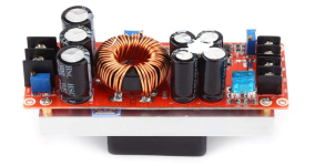
600W Aluminum Plate DC-DC Boost Converter Adjustable 10A Step Up Constant Current Power Supply Module Led Driver
 

Attachments

  • Screenshot_20230219_135629_edit_1093314787020147.jpg
    Screenshot_20230219_135629_edit_1093314787020147.jpg
    504.9 KB · Views: 16
Thank you very much for the help and ideas!
I have tried a 1200W DC boost converter before:
1676882111160.png

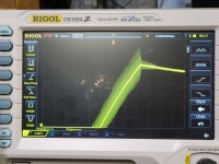
However, this one has voltage overshoot:
20210220_161554 (1).jpg


Maybe there is a way to have them slowly ramp up in voltage?
Does the driver you recommend have any overshooting?

Thank you for referring me to the power electronics company, ill give them a go and see what happens.
 
In order to organize a soft start in such drivers, it is enough to solder a 10 mF capacitor to the terminals of the voltage adjustment potentiometer
 
Can definitely do that but it needs to wait till summer time due to me taking some national exams for a possible E.E scholarship
Good luck!

What do you think the cost would be to develop something like this?
Hours + material

I was thinking for brightness control, we can just control the 4 individual arrays for: 0, 25, 50, 75, 100%
It would technically be 4 individual drivers if done this way.
 
Good luck!

What do you think the cost would be to develop something like this?
Hours + material

I was thinking for brightness control, we can just control the 4 individual arrays for: 0, 25, 50, 75, 100%
It would technically be 4 individual drivers if done this way.
The BOM should not surpass 50 dollars.
 
Good luck!

What do you think the cost would be to develop something like this?
Hours + material

I was thinking for brightness control, we can just control the 4 individual arrays for: 0, 25, 50, 75, 100%
It would technically be 4 individual drivers if done this way.
Honesty I do not really have a solid number to give as some prototyping runs will need to be done to iron out any sort of bugs, besides that I expect it to be lower than the figure you have on your post.
 
In order to organize a soft start in such drivers, it is enough to solder a 10 mF capacitor to the terminals of the voltage adjustment potentiometer
Can you give me some more information on how to do a soft start? What exactly should this kindensator be and where exactly should it be soldered?
Is it the one in the picture?
 

Attachments

  • 2126533054-41338453.jpg
    2126533054-41338453.jpg
    63.5 KB · Views: 1
Can definitely do that but it needs to wait till summer time due to me taking some national exams for a possible E.E scholarship

Good luck to you. I got my BSEE back in the 1970s, but paid for it myself. Did qualify for Pell grants though.
 
I was able to contract develop a compact driver and firmware for a 50W laser array. Good learning process.
It took around 3500usd


1704262503946.png
1704262519745.png
1704262542668.png
 
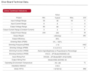
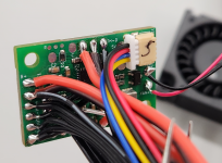
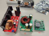
Made a compact custom driver for the 300W NUBM31T / NUBM36
V3:
3A, 82V
97.45% efficiency at 3A


I out: 0~3.5A
V in: 35~60V
V out: 60~90V


All components are on the top of the PCB and a heatsink is on the bottom.
I don't know how this will perform for thousands of hours.

1706156411666.png
 
Last edited:


Back
Top