Welcome to Laser Pointer Forums - discuss green laser pointers, blue laser pointers, and all types of lasers

LPF Donation via Stripe | LPF Donation - Other Methods

Links below open in new window

ArcticMyst Security by Avery

Another quick few questions

MA257

0
Joined
Mar 25, 2011
Messages
33
Points
0
I bought a 300mW 808nm diode long tima ago and im revisiting it. My question is:
Its a 300mW output and its op. voltage is 2.2. So does that mean it uses 136mA input?

I also bought some aixiz drivers because they were cheap and i didnt want to make anymore L317T drivers. I will be using these for both my 808nm 300mW and 650nm 250mW. Second question:

The driver requires 3.7v to operate at 3.2v 125mA output (5.6 ohm resistors)for my 650nm but, if i use a 14500 at 3.6v 800mA can i alter the resistors to output less voltage and more current for my 808nm (2.2v and my question above) or use a different battery.

Third question,
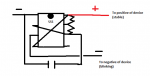
I want to use a 555 circut to create a strobe affect for my lasers using TTL on my aixiz drivers but the problem is that TTL requires 2-6v+ to activate the TTL and the modulation of energy is a negative output: Can i switch it to positive output somehow so that it blinks a positive current not a negative one (see pic below, current timer circut setup)?

Last question:
A 1.5v battery+ 1.5vbattery=3v of power but, does 320mA battery+ 320mA=320mA

Thanks guys for all who will help me:D
 

Attachments

  • Untitled.png
    Untitled.png
    9.2 KB · Views: 195
Last edited:


Joined
Dec 23, 2007
Messages
2,494
Points
0
Your post is a little confusing, if you would clarify a few things for me I will try to help.

The diode should have come with a recommended current to run it at. There is no linear relationship between optical power out and voltage and current in as you seem to be calculating it now. Where did you get the diode? Can you go back and look for some specs?

Which aixiz drivers are you talking about, they have several. If you are asking about the little red ones then there should be an adjustable resistor (or Pot) to set output current. The resistors they come with should fit the range for both of your diodes just fine, so don't worry about changing them. The voltage for your 808nm diode is lower so the driver should be able to keep the current up, but I've never tested that myself. I don't even know if that driver will work for a 808 diode, though I don't see why it wouldn't. You may have to increase the voltage to get the current to something usable but you won't know till you try.

They should be constant current drivers so the diode will regulate voltage on it's own.

The TTL input on these drivers turns the laser on with 2.5V+ on the TTL input pin to work. To pulse the diode you simply need to add a source of pulsed 2.5V+ power to the TTL pin. This driver will not work without a positive voltage higher than 2.5V on that TTL pin. If you are using the same power supply for both the TTL and driver input then you need to solder a 1N4xxx diode between the two pins.

Of course this is all assuming you are using the driver I think you are. I would suggest ditching that driver though, it will probably cause you way more trouble than you are ready to deal with.
 
Joined
Sep 12, 2007
Messages
9,399
Points
113
Its a 300mW output and its op. voltage is 2.2. So does that mean it uses 136mA input?

I see what you did there. 2.2*.136 = 300mW INPUT. Only if it is 100% efficient will the output be 300mW :). More like 250-400mA.
 

MA257

0
Joined
Mar 25, 2011
Messages
33
Points
0
I see what you did there. 2.2*.136 = 300mW INPUT. Only if it is 100% efficient will the output be 300mW :). More like 250-400mA.

oh yeah well i forgot that we dont lve in a perfect physics world. But i also need a reply on the 555 i cant get it right. I understand that the TTL needs positive current but my knowledge of the 555 is that pin 3 actually pulses negative enrgy instead of positive i need some help on how to rewire it to output positive pulse instead of negative

Well also if thr diode requires 2.2v at 400mA i need a driver with high amperage and low voltage or will 3v kill my diode?

nvm guys i got the 555 timer figured out i might make a post
 
Last edited:

wby300

0
Joined
Dec 18, 2011
Messages
104
Points
18
Last question:
A 1.5v battery+ 1.5vbattery=3v of power but, does 320mA battery+ 320mA=320mA

Connecting in Series
When connecting your batteries in Series you are doubling the voltage while maintaining the same capacity rating (amp hours). This might be used in a scooter, Power Wheels kids vehicle, or other applications. Just use a jumper wire between the negative of the first battery and the positive of the second battery. Run your negative wire off of the open connector from the first battery and your positive off of the open connector on your second battery.

Connecting in Parallel
When connecting in Parallel you are doubling the capacity (amp hours) of the battery while maintaining the voltage of one of the individual batteries. This would be used in applications such as laptop batteries, some scooters, some ups backups, etc. Use a jumper wire between the positives of both batteries and another jumper wire between the negatives of both batteries. Connect your positive and negative wires to the same battery to run to your application.

media.nl


Top