Welcome to Laser Pointer Forums - discuss green laser pointers, blue laser pointers, and all types of lasers

Buy Site Supporter Role (remove some ads) | LPF Donations

Links below open in new window

FrozenGate by Avery

4.36 Volts for M140 dide too low ?

Shobos

0
Joined
May 12, 2014
Messages
84
Points
0
Hello, while rnning M140 from driver I measured the voltage and it was 4.36 volts wich kinda seems a bit low for M140, right ? The driver is 2.0 amp LM358 IC with Mosfet, Im running driver off an 7 volt fixed votage PSU, driver is set at max current but the didoe is just "eating" 900-1000ma.... Might there be just too much voltage drop ? Should I increase the input voltage ?

P.S the multimeter IS calibrated and is 0.1% accurate
 
Last edited:


Hello, while rnning M140 from driver I measured the voltage and it was 4.36 volts wich kinda seems a bit low for M140, right ?

4.36V isn't unusual for an M140 at 1A.

The driver is 2.0 amp LM358 IC with Mosfet, Im running driver off an 7 volt fixed votage PSU, driver is set at max current but the didoe is just "eating" 900-1000ma.... Might there be just too much voltage drop ? Should I increase the input voltage ?

P.S the multimeter IS calibrated and is 0.1% accurate

That is already almost 3V difference
between input and output. There is
something else going on here.
 
Last edited:
That is already almost 3V difference
between input and output. There is
something else going on here.

I got the driver from Odicforce, in the spec it said too that it requires x3 3.7v li'ons. I asked Odic personally and he said the ideal voltage for the input should be 8-8.5 volts....:yabbem:

P.S The driver is set at almost 2 amps, the diode just isn't "eating" the current, but the output is of the diode is about 1W aka 1ma=1mw so I guess diode is working properly.... :(
 
Last edited:
It's often forgotten to include 1.25V on the current sense resistor when calculating linear regs like lm317. It needs 3.5V more than the load as a bare minimum, I believe.
 
Cyp, the driver is an LM358 op amp + pass transistor linear driver.

but the output is of the diode is about 1W aka 1ma=1mw so I guess diode is working properly.... :(

Where did you get that info? The only way to know output power is to measure it with an LPM.

As for "eating" the current, it is obvious the diode can take more. The driver can't supply what the diode needs. Maybe you had something wired wrong. Can you post a pic of your setup?
 
Cyp, the driver is an LM358 op amp + pass transistor linear driver.


Where did you get that info? The only way to know output power is to measure it with an LPM.

As for "eating" the current, it is obvious the diode can take more. The driver can't supply what the diode needs. Maybe you had something wired wrong. Can you post a pic of your setup?


I know it's a very rough measure, I saw power to ma charts for M140 using 3 element glass lens. anyway, I measured the the mw using IR thermometer method and I it turns out abut 950mw. I think it is pretty accurate reading because this laser can do things 1W should do, igniting match the hard way etc lol

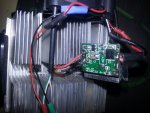
The problem is that I had this problem previously sing 2W boost driver, might it be, that the leads of the diode have broken inside and there is a big resistance and it cant deliver the current ? Here are some pics. Im using 7v VSB rail for driver. Im also using thick copper wires for the driver, the other wires are for the fans.

The drive FET is an NPN transistor with absolute maximum rating of 3 amps, the FET IS heatsinked using thermal glue.

P.S nothing gets hot.
 

Attachments

  • rsz_img_20141122_022323.jpg
    rsz_img_20141122_022323.jpg
    119 KB · Views: 81
  • rsz_img_20141122_022408.jpg
    rsz_img_20141122_022408.jpg
    114.3 KB · Views: 73
Last edited:
I have seen these drivers before and
actually have one right here. They are in
some of the 301-303 style lasers and a few
others. It's a shame you glued the board
down because it would be helpful to see
what is on the other side. There is a
large resistor there. If it's a 1Ω, then
increasing the voltage may actually work.
The driver may also be limited to 1A even
though it is capable of more.

I'm also confused by your statement about
the transistor. An NPN and a FET are not
the same thing. It can be either NPN or a
FET. not both. We need to be measuring
currents here anyway, not voltages so
much. How much current is actually going
into the driver? Does it change with
slightly more or less voltage?

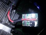
I took the heatsink off, take a look !

Seems to be 1ohm but There are actually two of them (ive seen these drivers previously in ebay too, all of them had one resistor tho)

Increasing voltage didn't help - 7 v fixed to 6x 1.5v = 9 volts batteries (at load about 8.4) made NO difference in current.Sorry, I thought they were same thing, I was absolutely wrong ! Datasheet says its an NPN Epitaxial Planar transistor. Now measuring with analog calibrated amp meter it is somewhere between 1200 and 1300ma! pot, as You can see, is set at max.

Thanks in advance.
 

Attachments

  • rsz_img_20141122_070334.jpg
    rsz_img_20141122_070334.jpg
    91.7 KB · Views: 67
Last edited:
Not all alkaline cells can push 1.8A, so
this could be another problem as well.
These drivers have a protection diode,
marked D1 on the board. I think that is
dropping enough voltage to dropout the
driver at 7V. Try soldering a wire across
it to short it out and see if it gives a
little more current. Be careful, though.
Turn the pot down before doing that. M140s
should only be run at 1.8A.

These can, I shorted the battery to my 6 amp meter and it maxed it out, they are ''super heavy duty'' lol :wave:

No success, still the same power.... Nothings changed.
 
I think then that this driver is limited to
1.2A. About the only way to get it to put
out more would be to change out the 43k
resistor (marked 433) with a 15k. If you
can find one marked 223, you could solder
it on top of the 433 and would make it
about 14.5k. Or if you can find one marked
153, remove the 433 and put that one in its
place. Again, be careful when you do this
to turn down the pot. It will change the
setpoint and could end up putting out over
2A.


Back
Top