- Joined
- Jan 14, 2009
- Messages
- 1,452
- Points
- 83
Hey ,
Well after a while I decided to try and make a variable constant current source with modulation for diode testing
The circuit if partly from a PFD form analogue devices .
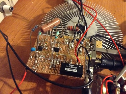
The basis setup is 2 op-amps one being used to drive the mosfet and the second is the current sense and feedback .
With a gain of 20 and a voltage present on the first opamp non inverting input of 5 volts the sense resistor is 20/5V to give 250mV across the resistor , then that is selected for that drop and the max current you want .
In my build it did drift above this as with a 0.03 Ohm resistor I get 10A at 5.4V , i'm not to sure why as with a 0.03 ohm sense I was aiming for 8.3A max .
0.250mV/0.03Ohm = 8.33333333333A , 0.250mV*20 Gain = 5V
Second thing I noticed is even at 250mV drop over the sense resistor it gets untouchably hot even though its a 5W resistor dissipating 4W worst case
The circuit runs from a 5V to +/-12V DC-DC converter .
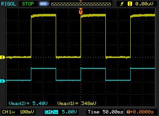
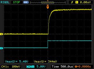
I wanted to ask as there are people on here with a lot more driver experience do these scope outputs look ok to you ? the load is two 150A diodes with drop of 1.65V each but as this is the first driver i've ever done past a LM317 I wanted to see what others thought before I risk a laser diode .
Supply is 5 volts and in the test the driver was driven with a 10Hz square wave but in my final design a voltage divider will be used to set the current of the diode and then on and off with 5 volts from a small DC-DC converter .
Both shots are at 10Hz , 0 - 11A Current ( 10A ? ) , there is ripple at about 20mV - 30mV , Blue trace is modulation and yellow is voltage across the sense resistor .
 NewFile3 by TwirlyWhirly555, on Flickr
 NewFile4 by TwirlyWhirly555, on Flickr
 IMG_0721[1] by TwirlyWhirly555, on Flickr
Well after a while I decided to try and make a variable constant current source with modulation for diode testing
The circuit if partly from a PFD form analogue devices .
The basis setup is 2 op-amps one being used to drive the mosfet and the second is the current sense and feedback .
With a gain of 20 and a voltage present on the first opamp non inverting input of 5 volts the sense resistor is 20/5V to give 250mV across the resistor , then that is selected for that drop and the max current you want .
In my build it did drift above this as with a 0.03 Ohm resistor I get 10A at 5.4V , i'm not to sure why as with a 0.03 ohm sense I was aiming for 8.3A max .
0.250mV/0.03Ohm = 8.33333333333A , 0.250mV*20 Gain = 5V
Second thing I noticed is even at 250mV drop over the sense resistor it gets untouchably hot even though its a 5W resistor dissipating 4W worst case
The circuit runs from a 5V to +/-12V DC-DC converter .
I wanted to ask as there are people on here with a lot more driver experience do these scope outputs look ok to you ? the load is two 150A diodes with drop of 1.65V each but as this is the first driver i've ever done past a LM317 I wanted to see what others thought before I risk a laser diode .
Supply is 5 volts and in the test the driver was driven with a 10Hz square wave but in my final design a voltage divider will be used to set the current of the diode and then on and off with 5 volts from a small DC-DC converter .
Both shots are at 10Hz , 0 - 11A Current ( 10A ? ) , there is ripple at about 20mV - 30mV , Blue trace is modulation and yellow is voltage across the sense resistor .
 NewFile3 by TwirlyWhirly555, on Flickr
 NewFile4 by TwirlyWhirly555, on Flickr
 IMG_0721[1] by TwirlyWhirly555, on Flickr
Last edited:


