Hello! I'm trying my hand at designing a simple buck driver, and this is what I have so far: I'm confused/looking for advice on a couple things (or anything you notice I did wrong, I'm still a noob so any advice is appreciated) if anyone would be willing to lend some time. Thank you all in advance!
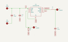
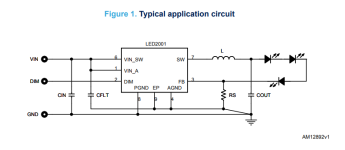
Is a single capacitor to ground sufficient for output filtering? The datasheet sample application only had a single capacitor on the output for filtering, and when I google output filtering with capacitors it's usually a single capacitor connected to ground. But when I look at other buck drivers it's usually a system of 4-6 capacitors on the output (particularly giannis' open source buck driver with 6 capacitors for output filtering). If it isn't, how would I determine what capacitor values and types to use?
Are the two capacitors shown sufficient for input filtering, and how would I determine the value of C3 connected to GNDA?
Are there particular considerations I should take in capacitor placement (or just general part placement) when making the actual PCB design?
My current schematic:

Sample application circuit from datasheet:

Is a single capacitor to ground sufficient for output filtering? The datasheet sample application only had a single capacitor on the output for filtering, and when I google output filtering with capacitors it's usually a single capacitor connected to ground. But when I look at other buck drivers it's usually a system of 4-6 capacitors on the output (particularly giannis' open source buck driver with 6 capacitors for output filtering). If it isn't, how would I determine what capacitor values and types to use?
Are the two capacitors shown sufficient for input filtering, and how would I determine the value of C3 connected to GNDA?
Are there particular considerations I should take in capacitor placement (or just general part placement) when making the actual PCB design?
My current schematic:

Sample application circuit from datasheet:


