

- Joined
- Jul 28, 2010
- Messages
- 89
- Points
- 0
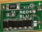
OK now that i know where to point the arrow to measure the Current an that i have to have both blue dots solder together an the two red with a gap.
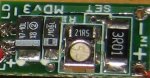
but first where do i put the needles (1R00) or (2001), one on each side right.
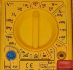
but now that i put the arrow to the right side where it say 200m above 5A an using a 9V battery "the square one." nothing show, no number but when i change it to the left upper side where it say 200 under the 500 it just tells me 7.9.
oh an then i change the red cable to the 5A an putting a needle to each side of the 2001 tells me 0.10 an i heard that its kind of (110mA)
but should i trust it.
(the picture that you see on the bottom of the MM is the one i have also the test load aka dummy, an the driver)
:thanks::thanks:
but first where do i put the needles (1R00) or (2001), one on each side right.
but now that i put the arrow to the right side where it say 200m above 5A an using a 9V battery "the square one." nothing show, no number but when i change it to the left upper side where it say 200 under the 500 it just tells me 7.9.
oh an then i change the red cable to the 5A an putting a needle to each side of the 2001 tells me 0.10 an i heard that its kind of (110mA)
but should i trust it.
(the picture that you see on the bottom of the MM is the one i have also the test load aka dummy, an the driver)
:thanks::thanks:


")
