- Joined
- Jan 14, 2009
- Messages
- 1,452
- Points
- 83
Hey all ")
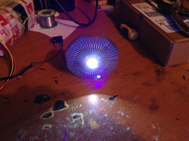
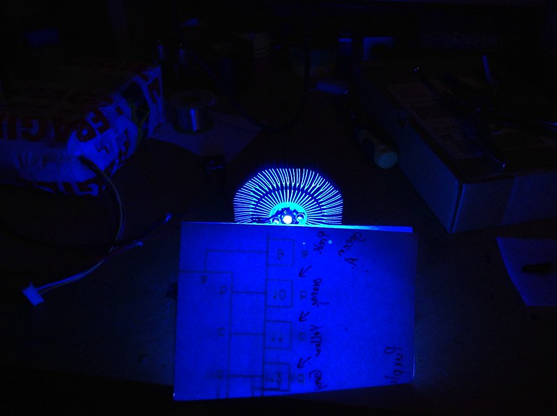
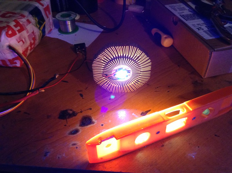
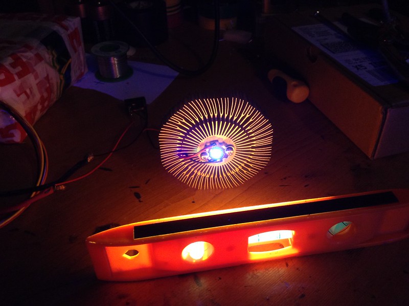
I have seen a few threads show up on UV 365nm leds and after taking the dive I have ordered the parts to build my own UV 635nm Torch .
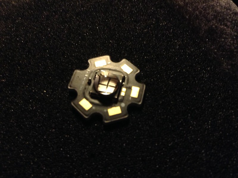
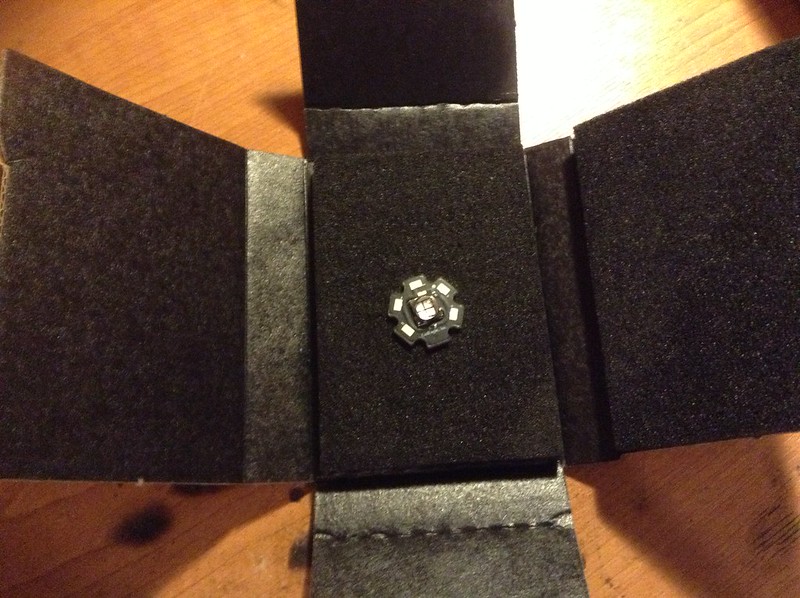
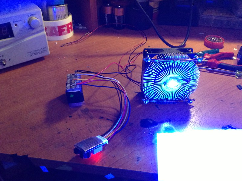
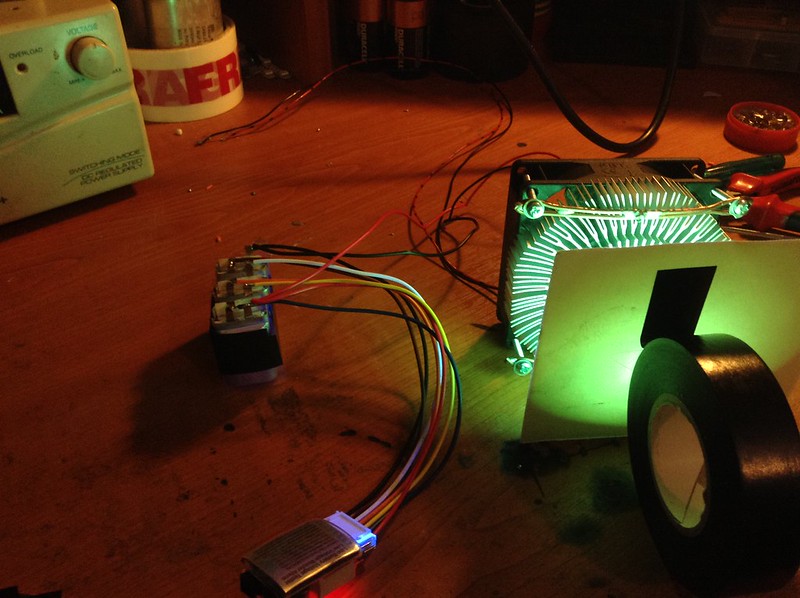
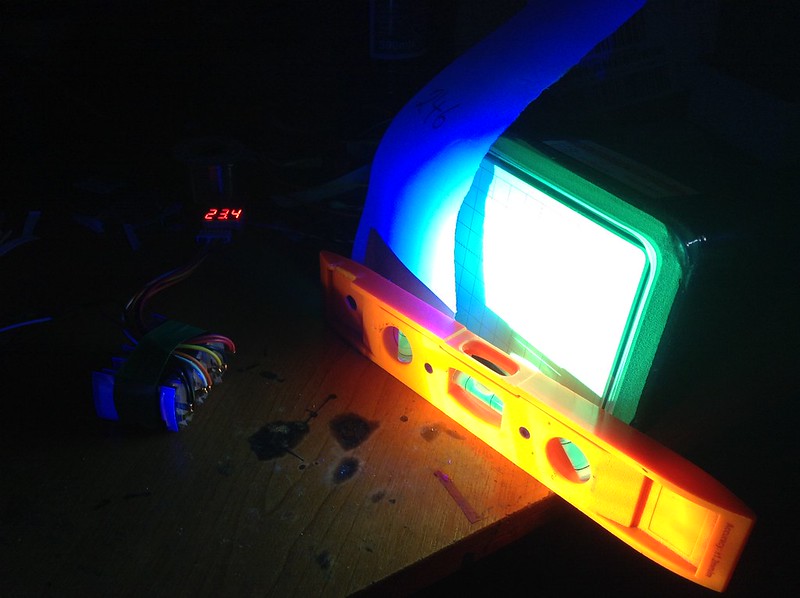
The Led that I plan to use is a LedEngine 11 Watt 365nm MCPCB mounted led , the led consists of 4 300mW dies and they are all wired in series for a running voltage of 16.8 Volts @ 700 mA drive current .
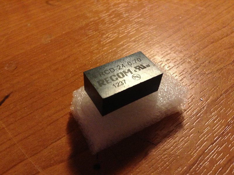
The Driver is a "puckdrive" 700mA constant current , dimmable driver with 4 - 32 Volts input range .
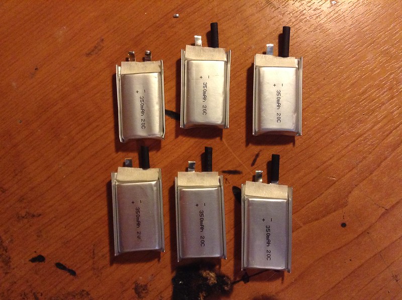
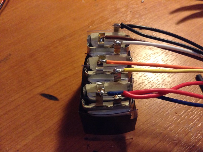
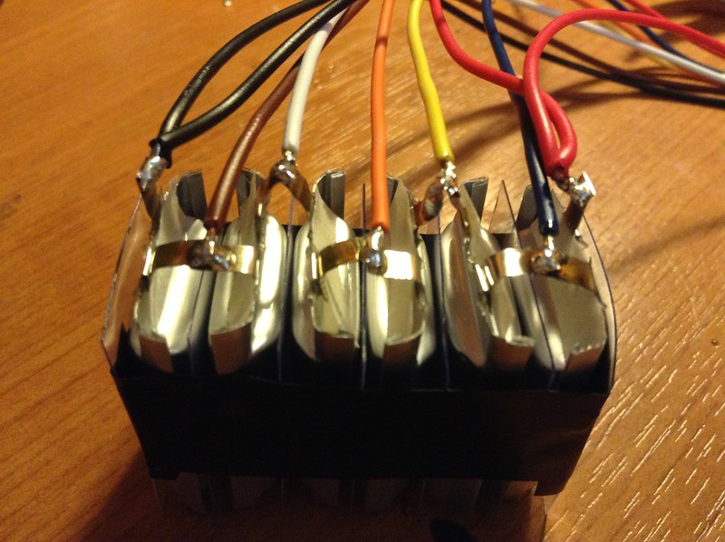
The power source is a 6 cell Lipo pack that I am putting together suing 350mA 20C cells , in this case they will be run at 2C , the fully charged voltage is 25 Volts and when the cells drop to 3.7 volts , around 22.2 Volts . The Cells measure 30mm x21mm x 7mm each .
I did plan to use a 5 cell setup , but at 3.7 cell voltage the pack would be 18.5 and the led driver requires Vin to be 2.5 Volts + led Vf and I wanted to be abit above that even when batteries are nearly at 80% empty
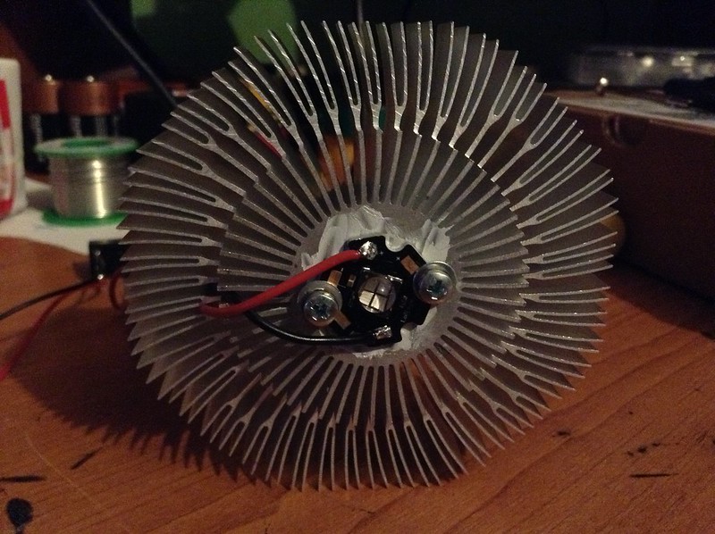
Cooling is a heatsink setup with a ultraflat aluminium/acetone heat pipe that is 20mm Wide x 1mm thick and 200mm long , I do have a 30mm wide x 1.6mm thick version aswell if the first one dosent work , but for a heat load of 10 watts max there should be no problem .
The idea is to have the led at the front of the housing with it bolted to a square pice of aluminium with the heatpipe sandwiched in-between , then the heatpipe bends 90 degree round to the side where the 120mm long x 40mm heatsink will be mounted by the side of the battery compartment .
It may not end up working the way I planed , But ill soon find out , the led does like to be run fairly cool so hopefully the heatpipe setup will work , plus I will have forced air cooling on the heatsinks .
Pics will follow as I build it and when I find my camer cable
Twirly .
I have seen a few threads show up on UV 365nm leds and after taking the dive I have ordered the parts to build my own UV 635nm Torch .
The Led that I plan to use is a LedEngine 11 Watt 365nm MCPCB mounted led , the led consists of 4 300mW dies and they are all wired in series for a running voltage of 16.8 Volts @ 700 mA drive current .
The Driver is a "puckdrive" 700mA constant current , dimmable driver with 4 - 32 Volts input range .
The power source is a 6 cell Lipo pack that I am putting together suing 350mA 20C cells , in this case they will be run at 2C , the fully charged voltage is 25 Volts and when the cells drop to 3.7 volts , around 22.2 Volts . The Cells measure 30mm x21mm x 7mm each .
I did plan to use a 5 cell setup , but at 3.7 cell voltage the pack would be 18.5 and the led driver requires Vin to be 2.5 Volts + led Vf and I wanted to be abit above that even when batteries are nearly at 80% empty
Cooling is a heatsink setup with a ultraflat aluminium/acetone heat pipe that is 20mm Wide x 1mm thick and 200mm long , I do have a 30mm wide x 1.6mm thick version aswell if the first one dosent work , but for a heat load of 10 watts max there should be no problem .
The idea is to have the led at the front of the housing with it bolted to a square pice of aluminium with the heatpipe sandwiched in-between , then the heatpipe bends 90 degree round to the side where the 120mm long x 40mm heatsink will be mounted by the side of the battery compartment .
It may not end up working the way I planed , But ill soon find out , the led does like to be run fairly cool so hopefully the heatpipe setup will work , plus I will have forced air cooling on the heatsinks .
Pics will follow as I build it and when I find my camer cable
Twirly .
Last edited: