

- Joined
- May 24, 2009
- Messages
- 53
- Points
- 8
This is my first guide if you want to call it that. i just wanted to share my experience with the o-like module
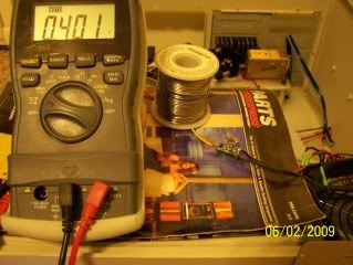
pics of driver:
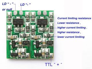
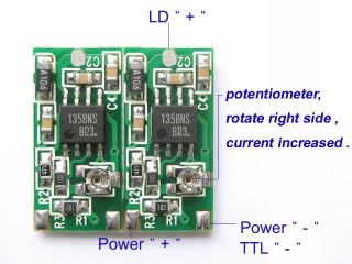
Driver is based on the LM358N 8pin chip " thanks diachi for pointing that out"
a pdf file can be found http://www.fairchildsemi.com/ds/LM/LM258.pdf
i would suggest not to exceed 5.5v input as i pushed it up to 7v and fried a lead on the board "but it was repairable") "
"
my intended use was for the lpc-815 open can diode but was unable to exceed the factory settings of ~250ma.
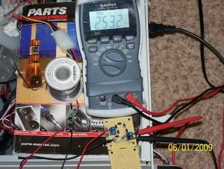
measured with dummyload at hi ttl
There are two states of power low and hi. Driver will remain at low until trigger by ttl input " i use 5v+ " you can defeat this by simply drilling a small hole through and filling with solder. or possibly soldering low resistor to high resistor OOPS. not sure how safe that is. you could also make a wire trace or solder trace but this will complicate install in aixiz module it that is your intent.
the mod:
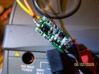
i did tests by piggyback additional 10ohm resistors until i reached an acceptable current range. each additional resistor drops the resistance thereby increasing the current. Pictured is the original surface mount 10 ohms + 3 additional 10 ohms should be about 2.5R but with the varied tolerance measured 2 ohms.
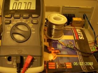
below is the testing hi ttl output with the piggyback resistors
and here is the testing of the unchanged low ttl but may be modified to ~40ma to possibly improve blanking if needed. not sure yet.
 l
l
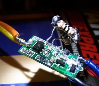
I wanted to put this in the aixiz module but not with this mountain of resistors that might fall off or short out.
since i already had a spare driver with bad lead i removed a 1.5 ohm resistor marked (1R5) from the top backside and replaced the high current limiting resistor
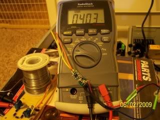
i then made my final adjustments again with the new resistor in place
and spent the next 2 hours fixing everything i broke trying to get it to fit in the aixiz module LOL:thinking:
my final solution was drill out the rear end with a 3/8" bit and patiently screw it on being careful not to break the leads on the can as i soldered it directly to the pcb.
anyhow here is the fully loaded 400ma aixiz module with ttl just begging to be mounted in my tec cooler "almost done with that !!"
be sure you don't run it very long as it will get warm very fast w/o a heatsink
GOOD LUCK!!!!
pics of driver:
Driver is based on the LM358N 8pin chip " thanks diachi for pointing that out"
a pdf file can be found http://www.fairchildsemi.com/ds/LM/LM258.pdf
i would suggest not to exceed 5.5v input as i pushed it up to 7v and fried a lead on the board "but it was repairable
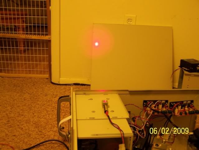
"my intended use was for the lpc-815 open can diode but was unable to exceed the factory settings of ~250ma.
measured with dummyload at hi ttl
There are two states of power low and hi. Driver will remain at low until trigger by ttl input " i use 5v+ " you can defeat this by simply drilling a small hole through and filling with solder. or possibly soldering low resistor to high resistor OOPS. not sure how safe that is. you could also make a wire trace or solder trace but this will complicate install in aixiz module it that is your intent.
the mod:
i did tests by piggyback additional 10ohm resistors until i reached an acceptable current range. each additional resistor drops the resistance thereby increasing the current. Pictured is the original surface mount 10 ohms + 3 additional 10 ohms should be about 2.5R but with the varied tolerance measured 2 ohms.
below is the testing hi ttl output with the piggyback resistors
and here is the testing of the unchanged low ttl but may be modified to ~40ma to possibly improve blanking if needed. not sure yet.
I wanted to put this in the aixiz module but not with this mountain of resistors that might fall off or short out.
since i already had a spare driver with bad lead i removed a 1.5 ohm resistor marked (1R5) from the top backside and replaced the high current limiting resistor
i then made my final adjustments again with the new resistor in place
and spent the next 2 hours fixing everything i broke trying to get it to fit in the aixiz module LOL:thinking:
my final solution was drill out the rear end with a 3/8" bit and patiently screw it on being careful not to break the leads on the can as i soldered it directly to the pcb.
anyhow here is the fully loaded 400ma aixiz module with ttl just begging to be mounted in my tec cooler
"almost done with that !!"
be sure you don't run it very long as it will get warm very fast w/o a heatsink
GOOD LUCK!!!!
Last edited:

