- Joined
- Oct 21, 2008
- Messages
- 100
- Points
- 18
Hello guys,
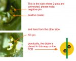
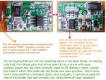
My dilda v2 diode died , so i decided to upgrade it to blu-ray one, but i still think that the stock driver wich i desoldered is working ok.So i want to reuse it with new LCC diode pressed into aixiz module and using this driver.My question is where do i connect the diode positive and negative pins?I wont need the case pin because i am not going to host it.
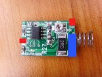
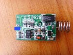
Here are some pics of the drivers both sides


And also where is the ground input?(somewhere near the spring)
My dilda v2 diode died , so i decided to upgrade it to blu-ray one, but i still think that the stock driver wich i desoldered is working ok.So i want to reuse it with new LCC diode pressed into aixiz module and using this driver.My question is where do i connect the diode positive and negative pins?I wont need the case pin because i am not going to host it.
Here are some pics of the drivers both sides
And also where is the ground input?(somewhere near the spring)


")