Welcome to Laser Pointer Forums - discuss green laser pointers, blue laser pointers, and all types of lasers

LPF Donation via Stripe | LPF Donation - Other Methods

Links below open in new window

ArcticMyst Security by Avery

Adjustable Micro-Driver and 803t Questions

Joined
Oct 31, 2008
Messages
147
Points
0
I'm considering using rkcstar's adjustable driver in the 30-150 mA range for my 803t build. My questions are as follows: First, is it safe to tune a running diode? Second, at this approximately specified current range, could I basically run an 803t at min->max current supplied by this driver safely? Third, does the potentiometer"lock" when I have reached its min/max setting? Fourth, even if I can't tune the diode continuously as it runs, could I tune this driver just using the 803t diode and a DMM instead of with a test load? And finally, is it safe to run the 803t diode at or near the minimum lasing threshold? I ask these questions mainly because I'd like to be able to run this diode at low mW output for normal use, but have the option of running it near maximum output for short periods of time as well.

Thanks in advance for any answers given. :p


Joined
Jul 24, 2007
Messages
2,749
Points
0
I'm considering using rkcstar's adjustable driver in the 30-150 mA range for my 803t build. My questions are as follows:
First, is it safe to tune a running diode?
If you put a 1ohm resistor between the power supply and the Rkcstr, you can measure the ma with the laser powered up, but go very carefully as the top end of the range is in the killing zone for 803T's
Second, at this approximately specified current range, could I basically run an 803t at min->max current supplied by this driver safely?
No, see comment above
Third, does the potentiometer"lock" when I have reached its min/max setting?
No, the pot is very small and very fragile, you need to go very carefully with it
Fourth, even if I can't tune the diode continuously as it runs, could I tune this driver just using the 803t diode and a DMM instead of with a test load?
Answered above...but a test load is always a good idea
And finally, is it safe to run the 803t diode at or near the minimum lasing threshold?
I see no reason why not, but you won't get much of an output
I ask these questions mainly because I'd like to be able to run this diode at low mW output for normal use, but have the option of running it near maximum output for short periods of time as well.
Now we come to the crux of these questions, realisticly the Rkcstr is not the right driver for someone who wants to constantly play with output power, it is really a "set and forget" circuit.
A better driver for playing with is the LM317 driver, you can put a large pot in the circuit with a knob you can twiddle and as long as the fixed resistor is the correct value, you should not be able to over power the LD


Regards rog8811
 

kendon

0
Joined
Jan 12, 2009
Messages
154
Points
0
i threw together a little excel sheet (works in OOo) to make calculating the resistor values easier.

i hope it helps, i set 10-20-50-100 as values for the available valuable resistors b/c that are the values i can buy here. if you have access to other values let me know, i will change the formula then.

the minimum current isn't determined exactly, but i think it will always be below lasing threshold (someone correct me if i am wrong, what is usually the threshold anyway?) so if you want to go from 200 - 250mA you won't need a 100ohm pot. if i can figure out how to get that with excel formula i will add it.

[edit] nevermind, i changed the sheet, you can enter min current now. keep in mind that the absolute minimum current will be less than what you entered, b/c of the availabe pot values.[/edit]

always check with DMM and dummyload what you calculated, i am not responsible for your blown diodes if you don't check!
 

Attachments

  • ddlrescalculator_kendon_xls_001.zip
    5.2 KB · Views: 29
Joined
Oct 31, 2008
Messages
147
Points
0
Great answers, thanks rog. And kendon, nice work there man. :p

So, looks like I can get the LM317 real cheap, but is there someone here who sells a PCB driver with said LM317 and big pot pre-installed? I'd prefer a small etched PCB over something I breadboard together myself.
 

kendon

0
Joined
Jan 12, 2009
Messages
154
Points
0
you can make it pretty small, and it's not that difficult at all. the driver on the left is my second build, took me 20 mins maybe. the one on the right is my first try, i just started soldering, and that's how it looks, but it works.

the pot on the smaller driver has 25 turns for 0-100 ohm, which makes it way easier to adjust.

i think i will make one with an included test load and a switch for quick adjustments, as soon as i get parts for more. for the small one i had to harvest some kind of rf amplifier for the cap and the 317...   :)

and if someone could tip me off how to quick-n-dirty draw a board layout i will give you the wiring on the solder side  ::)
 

Attachments

  • ddl.jpg
    ddl.jpg
    56.8 KB · Views: 254
Joined
Oct 31, 2008
Messages
147
Points
0
Yeah, I've basically started something similar to what you're doing.  I figure I have plenty of room with an MXDL host, so time to see how this turns out. :p

Although, I'm curious, have there been any notable improvements to Daedal's original design?
 
Joined
Jul 24, 2007
Messages
2,749
Points
0
here you go, this shows 1 10ohm resistors for 803T.

Regards rog8811
 

Attachments

  • 803T_vero_layout_LM317_driver_002.jpg
    803T_vero_layout_LM317_driver_002.jpg
    58.7 KB · Views: 1,049

kendon

0
Joined
Jan 12, 2009
Messages
154
Points
0
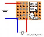
here's the layout for the board, but i didn't make it with veroboard like rog, i don't know how it is called. it just has solderpoints, you have to make all connections yourself. in this case you can just bend the legs of the components to the solder points, there is no additional wire necessary.
 

Attachments

  • ddl_layout_kendon.jpg
    ddl_layout_kendon.jpg
    14.5 KB · Views: 452
Joined
Oct 31, 2008
Messages
147
Points
0
That looks great. However, tests have shown that the dropout voltage is about diode + 3 V? I don't think this is the optimal driver for me to run with two 3.6V RCRs.
 
Joined
Oct 31, 2008
Messages
147
Points
0
Sorry, I'm not worried about heating problems since the 803T only runs about 125mA maximum. Rather, I hear that even RCRs will start to sag in voltage after about 50% depletion and drop below the dropout voltage for this driver.
 
Joined
Jul 24, 2007
Messages
2,749
Points
0
This has gone full circle, there is no doubt that the Rkcstr drive is better on voltage usage than the LM317 but as already pointed out the Rkcstr is not a driver that you can constantly adjust when built into an Aixiz module.
Unless you are prepared to do some microsurgery on the Rkcstr to bring out the pot connections you will not be able to fulfill both of your requirements.

Regards rog8811
 
Joined
Nov 24, 2007
Messages
65
Points
0
Try this driver by kernelpanic:

http://www.laserpointerforums.com/forums/YaBB.pl?num=1220866048

Don't use the very first schematic posted, use the second one posted by kernelpanic. It uses an opamp and a mosfet and will work with very small voltage difference between the batteries and the laser diode.

I breadboarded a version using a toshiba 2SK1112 for the mosfet that I got 50 on ebay for very cheap and it worked great.
 
Joined
Sep 8, 2008
Messages
182
Points
0
positron said:
Try this driver by kernelpanic:

http://www.laserpointerforums.com/forums/YaBB.pl?num=1220866048

Don't use the very first schematic posted, use the second one posted by kernelpanic. It uses an opamp and a mosfet and will work with very small voltage difference between the batteries and the laser diode.

I breadboarded a version using a toshiba 2SK1112 for the mosfet that I got 50 on ebay for very cheap and it worked great.

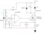
Normal mosfets like the 2sk1112 will work. But a logic level mosfet (like an IRL-510) will work better for battery powered circuits. Also I recommend NOT using a pot to adjust power on the fly. Better to use fixed resistors and a momentary SPDT push-button to activate 'burn mode'. (Schematic attached.)

If you decide to use this, calculate R1, R2 and R3 using the following-

R1 + R2 + R3 ~ 1000 ohms

Low power = 0.3 * R3 / (R1 + R2 + R3) in Amps.

High power  0.3 * (R3 + R2) / (R1 + R2 + R3) in Amps.

Example: Low power 50mA high power 126mA-
R1 = 620 Ohms
R2 = 270 Ohms
R3 = 180 Ohms

Diode drop is around .6V but varies with voltage. You'll want to verify the values and actual output current experimentally on a test load before risking an LD. Also don't omit the 1M resistor as it helps pull the input towards ground while the button is 'flipping'.

Hope this helps,
kernelpanic

[edit] The formulae above are approximate. Actual power will be slightly lower than calculated as the sense resistors form a parallel resistor network with the 1M resistor. But it'll get you close. ;) [/edit]
 

Attachments

  • driver-2mode.JPG
    driver-2mode.JPG
    29.7 KB · Views: 400


Top