Welcome to Laser Pointer Forums - discuss green laser pointers, blue laser pointers, and all types of lasers

LPF Donation via Stripe | LPF Donation - Other Methods

Links below open in new window

ArcticMyst Security by Avery

Conceptual design of anamorphic prisms on sinner focus ring. Pix!

Joined
Aug 16, 2013
Messages
971
Points
43
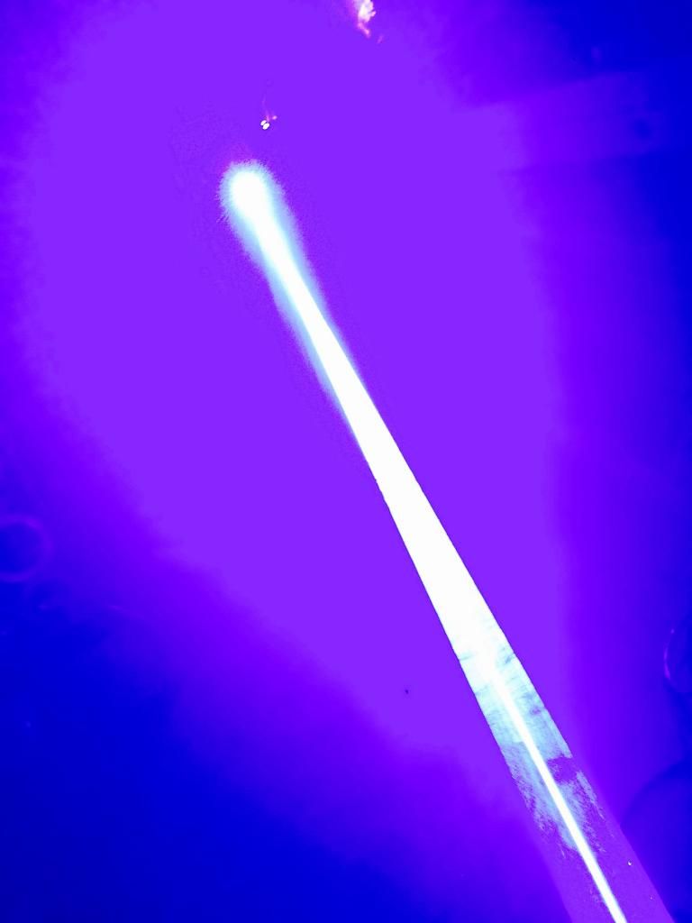
Check out this beam profile I got from my dual 3.5W. Correction would be nice but power was the point of that build. I still have some polarization to tweet but it forms a perfect + shape.

Mind you you're looking at 8+ watts. (Sorry for the size, can't edit that from my moble)
 
Last edited:


Joined
Feb 25, 2010
Messages
1,643
Points
113
Currently I have transferred the testing of the TS cylindrical lens pair to a platform which incorporates a custom LD holder I designed and machined.

The latest design is labeled as LDAM V10. The collimation lens is held stationary and a portion of the holder is adjustable in the X-Y direction. The LD is mounted in what is identified as the " T-Cylinder ". The LD is mounted in the T-Cylinder via a thermal epoxy fix.

This T cylinder can be adjusted up/down and in a radial fashion. Pressure is maintained with the component labeled the " Clamping Plate". Once optimal X-Y and radial positioning are achieved, the clamping plate is tightened down to lock the adjustment in place.

This unit is just another approach toward adjusting the P-73 or Oclaro 700 LD relative to the collimation lens centerline. The better the alignment, the lower the degree of any farfield aberration. The adjustable LD mount from LPS does the same thing, but, this unit makes the alignment process easier to accomplish. The downside is size and cost.

This large brass mount is not a component for any Hand Held unit but a very good design to use to optimize the results obtained with the P-73 or Oclaro 700 LD in the larger lab style format. I will continue my evaluation of the TS cylindrical pair in combination with the Oclaro 700 with this mount and set-up.

See pics of the new set-up sans the LD. Stay tuned for more fun with optics....

Oh and thanx LStalker for pointing out and explaining the issue of perpendicular vs. parallel raw LD divergence. This metric is typically listed on the LD data sheets and tells you to what degree of elipiticity you are dealing with and what optics you will need to hammer the beam to somewhat round.
 

Attachments

  • PLPP LDAM 10 General Arrangment.JPG
    PLPP LDAM 10 General Arrangment.JPG
    138.5 KB · Views: 210
  • TS with Oclaro A.jpg
    TS with Oclaro A.jpg
    155.8 KB · Views: 275
  • TS with Oclaro B.jpg
    TS with Oclaro B.jpg
    119.2 KB · Views: 244
  • TS with Oclaro C.jpg
    TS with Oclaro C.jpg
    122.3 KB · Views: 156
  • Mad Scientist #4.jpg
    Mad Scientist #4.jpg
    139.7 KB · Views: 157
Last edited:
Joined
Feb 25, 2010
Messages
1,643
Points
113
A little clarification as to why a mount such as the LDAM V10 works well with the P-73 or Oclaro 700 diode. We all know that the P-73 or Oclaro 700 are nasty diode's in the area of divergence.

Lighting Stalker noted they are also bad considering their high aspect ratio: perpendicular divergence vs. the parallel divergence....BAD....in that the aspect ratio between the two is quite high. Below is what I believe to be accurate concerning optics ( read: disclaimer due Optics Wizard in Training/Wanna'Be !! ).

First, we need to use the 2mm EFL collimation lens because the sooner we start to expand the slow axis.....the better results we get for correcting the divergence !!! By " sooner" , I mean we need to physically place the collimation lens in the optical path as close to the LD and the divergent rays as possible. The further away from the LD emitter, the greater the rays spread.

When the collimation lens is positioned only two (2) mm from the emitter......because the EFL ( Effective Focal Length) is 2mm on this lens...we capture the divergent rays and start to correct them before they spread. When we employ this method, we get the best results. The good results of this early correction are why we need to use a 2mm EFL collimation lens on these diodes.

Now...this close placement of the collimation lens to the LD has a downside...when the collimation lens is placed so close to the diode emitter....VERY small movements in the XY position of the diode itself are demanded to achieve perfect centering of the LD to the collimation lens centerline.

When poor centering of the LD to the collimation lens occur.......the far field geometry will look quite bad/distorted....with some serious aberrations. The better the centering, the cleaner the beam geometry presents at the far field.

This is why, for projector use, when using the P-73 or Oclaro 700, a typical set up uses the Adjustable Mount from Laser Show Parts. The LSP mount allows positioning of the LD relative to the collimation lens.....So does the LDAM V10

When using the LDAM V10, the X-Y movement of the LD is done with a bottom spring and three (3) additional set screws to achieve the optimal positioning. In a controlled and slow adjustable manner, the three (3) set screws move the T-cylinder up/down-left/right. The method to achieve centering is straight forward. Start by adjusting the X-Y screws so that the beam is perpendicular to the mount face, both up/down , then left/right. This adjustment is the main work.

Next, with the diode on, the collimation lens focused and no cylindricals present, observe the far field geometry. It will be a bar. Use the three (3) set screws to move the LD again, up/down-Left/right. When the bar appears to be most well defined, least bluried around the edges....then the X-Y adjustment is the best that can be achieved.

While the X-Y positioning is being set, the radial positioning is also being dialed in. Remember, the radial position of the LD needs to be such that as the beam enters the cylindrical correction lenses, the slow axis needs to be parallel to the centerline of the lenses. This parallel condition is easy to determine: When the diode is on, the collimation lens is focused and no cylindricals are present... the farfield geometry will be our old friend... the bar. This bar needs to be horizontal and parallel with your optical platform. That is all. The clamping plate applies spring loaded pressure to the back side of the component identified as the "T-Cylinder". The T-cylinder is a holder for the LD.

Again, after the optimal X-Y and radial position are achieved, the four (4) bolts on the rear face of the clamping plate are tightened down to lock the LD in the best position.

The LDAM V10 makes alignment of the P-73 / Oclaro 700 very easy !!! The bulk of the Brass construct also acts as a good heat sink for the LD.

In closing, this LD mount is fine for a lab style set-up, but alas... is not at all practical for the HH format. For the hand held format, the LSP adjustable mount must be used when working with the P-73 or the Oclaro 700 LD. This concept was demonstrated by the " Dragon's Head" build. I hope this explains a few things. Enjoy the ride !!

Note: Added pic...a select few will recognize this...R.Crumb...You ROCK !!!
 

Attachments

  • wizard-telescope_Hat and Title text 3.png
    wizard-telescope_Hat and Title text 3.png
    734 KB · Views: 100
  • Optics Agin.jpg
    Optics Agin.jpg
    117.9 KB · Views: 130
Last edited:
Joined
Feb 25, 2010
Messages
1,643
Points
113
A quick up date on the progress ( Or lack of progress ) with the EZ adaptor. I have not been successful using the TS cylindrical optics. They are great to work with....being the same size and geometry.....however...

I cannot get them to correct the output of the Oclaro 63193 Red 700mw LD as well as a set of 6X cylindrical I have. I believe the TS set is 3.25X and they may work fine for the 7475 Green or 7A75 Blue. I have a set of LSP 4X cylindrical's to experiment with and will see what they do. Work and the Holidays have been rather demanding. Happy New Year All !!!!:D
 
Last edited:
Joined
Aug 16, 2013
Messages
971
Points
43
It's funny you should comment on this; I was actually going to bump this thread earlier today but forgot until just now. Thanks for the progress update! well, even if they work best on the 520s and 445s that's still good. However, something to correct that horrible red Oclaro would be nice.
 
Joined
Feb 25, 2010
Messages
1,643
Points
113
It's funny you should comment on this; I was actually going to bump this thread earlier today but forgot until just now. Thanks for the progress update! well, even if they work best on the 520s and 445s that's still good. However, something to correct that horrible red Oclaro would be nice.

Well....I know we will get there for the red !! I know 5X and 6X have enough magnification to "hammer" that red beam into a reasonable farfield dot ( I have experimented with them). Not perfect....but good !!

It is just that ..... it's nice to have both optics the same size !! This leads to a simplified mount design !! ...which leads to a lower unit cost !! I have another lens option I will also be experimenting with. We will see !!

SOoooo.....this project is not abandoned...just real life gett'in the way :D

Happy New Year !!!
 
Last edited:


Top