Welcome to Laser Pointer Forums - discuss green laser pointers, blue laser pointers, and all types of lasers

LPF Donation via Stripe | LPF Donation - Other Methods

Links below open in new window

ArcticMyst Security by Avery

My LM3410x based Boost converters: Spark driver! PART 1

Joined
Jul 30, 2010
Messages
21
Points
0
Bear in mind that the design example they give is for 350mA. The coupling and output capsneed to be higher for your uses.

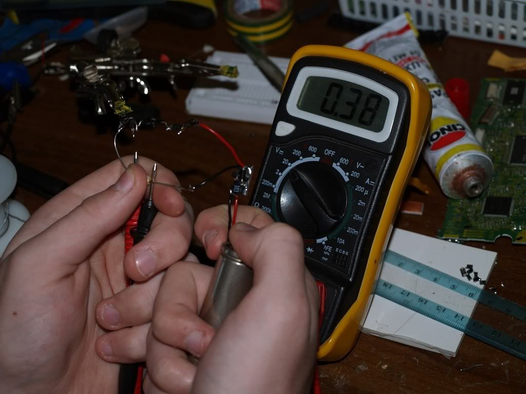
Well, i used all my 10microF in parallel but it didn't work... Set C1 (input) to 20microF, C2 (output) to 40microF and C3 (coupling) to 30microF... The LED turns on for about 5 seconds and then starts flashing... I'm using R1=0,22omh so i was expecting around 800mA at output, but only reached 440mA for a few seconds... then decreases to about 380mA and the LED starts flashing...

If i use R1=1ohm, i get around 190mA at output and the SEPIC works ok...

I'm running out of ideas... :cryyy:


Joined
Feb 5, 2008
Messages
6,252
Points
83
Hai folks, can't believe somebody's posting in this old thread, but anyway today I did some driver tests...

I used a coil and resistor found in Ultrafire WF-501B lamps from DX (9.90 for entire flashlight).

I managed to squieze out 750 mA stable out of LM3410X in SOT23-5 package at 5x 1n400x + 1ohm resistor load (445nm driver ).

Looks like this thing is tough.

Will upload picz in a few momentz.
 
Joined
Jul 30, 2010
Messages
21
Points
0
Hai folks, can't believe somebody's posting in this old thread, but anyway today I did some driver tests...

I used a coil and resistor found in Ultrafire WF-501B lamps from DX (9.90 for entire flashlight).

I managed to squieze out 750 mA stable out of LM3410X in SOT23-5 package at 5x 1n400x + 1ohm resistor load (445nm driver ).

Looks like this thing is tough.

Will upload picz in a few momentz.

Was in SEPIC mode or in boost mode?
 
Joined
Feb 5, 2008
Messages
6,252
Points
83
Was in SEPIC mode or in boost mode?
Boost mode, very first schematic on the datasheet's first page.

Picz time:
P8040012.jpg


That's the driver board.

This is compared to MicroBoostDrive:
P8040015.jpg

Big motherf***er, eh?

It was made for robjdixon , to fit his kryton host.

This is a bit smaller driver made for 380mA meant for 8x Bluray diode. Tested and works, OFC. 'Scyooz the mess on the PCB but that puddle of solder is actualy capable of powering an 8x :p

P8040269.jpg


P8040278.jpg


P8040280.jpg
 
Joined
Jul 30, 2010
Messages
21
Points
0
Hai folks, can't believe somebody's posting in this old thread, but anyway today I did some driver tests...

I used a coil and resistor found in Ultrafire WF-501B lamps from DX (9.90 for entire flashlight).

I managed to squieze out 750 mA stable out of LM3410X in SOT23-5 package at 5x 1n400x + 1ohm resistor load (445nm driver ).

Looks like this thing is tough.

Will upload picz in a few momentz.

So, to get 750mA from it, what values for C1 and C2 did you use?
 
Joined
Feb 5, 2008
Messages
6,252
Points
83
So, to get 750mA from it, what values for C1 and C2 did you use?
I don't know where exactly C1 and 2 are.

I name my capacitors like so:
Input capacitor - self explanatory
Schottky capacitor, the capacitor parralel to load AND schottky diode, shown in schematic.
LD capacitor - capacitor parralel only to LD itself.

Input and schottky capacitor should be around 10 uF, and LD capacitor should be around twice of schottky, so around 20uF, but bigger the better.

I used big tantalum capacitors in my two drivers for 380 and 760 mA.
See pictures.
 
Joined
Oct 25, 2007
Messages
221
Points
0
I've had no trouble getting over 1A in boost. I left sepic for the lower currents of red and some IR diodes.
 
Joined
Jul 30, 2010
Messages
21
Points
0
I've had no trouble getting over 1A in boost. I left sepic for the lower currents of red and some IR diodes.

Ok, i quit from the SEPIC design and now i'm using the boost design. Set Cin and Cout to 10microF and powered the circuit with 4,5V. I started with 190mA output current and raised it putting several 1ohm resistors in paralell. Up to 0,33ohm everything was fine, i was getting 520mA @ 5,66V output and the Vfb was always near 180mA. I had another resistor to get 760mA and the LED started flashing... Exactly like the SEPIC...
It feels like the LM3410 is shutting down when i try to pull some current from it.
I'll give it a last chance, i'm going to use my last LM3410 and build a PCB with a design closer to the demo board, just to know if the (poor) PCB design is getting influence.:yabbmad:
 

JLSE

1
Joined
Dec 13, 2007
Messages
3,580
Points
0
I wonder is it possible to power red LD with lithium ion battery in boost mode?


It is possible but you hit 2 problems... place a couple of diodes in series with the load. As long as you raise the vf of the load to 4.5v or higher it works. Problem #1 the efficiency suffers, but im not sure if the loss is more or less than in sepic. I have never tested that.

Prblem #2, you have to isolate the output ground from case - or you bypass your v-ref and the driver sends all its got, as shorting the v-ref to gnd is essentially a 0.0R r-set. Most reds have the - case pin, and this requires a workaround. Unless of course you get one of those PL GB case neutral diodes.
 
Last edited:
Joined
Feb 5, 2008
Messages
6,252
Points
83
It is possible but you hit 2 problems... place a couple of diodes in series with the load. As long as you raise the vf of the load to 4.5v or higher it works. Problem #1 the efficiency suffers, but im not sure if the loss is more or less than in sepic. I have never tested that.

Prblem #2, you have to isolate the output ground from case - or you bypass your v-ref and the driver sends all its got. Most reds have the - case pin, and this requires a workaround. Unless of course you get one of those PL GB case neutral diodes.
I see, placing some diodes in series is smart thing to do,
I need to etch some new boards...

Isolating diode from case of host is not problem.

Thanks.
 
Joined
Jul 30, 2010
Messages
21
Points
0
I don't know where exactly C1 and 2 are.

I name my capacitors like so:
Input capacitor - self explanatory
Schottky capacitor, the capacitor parralel to load AND schottky diode, shown in schematic.
LD capacitor - capacitor parralel only to LD itself.

Input and schottky capacitor should be around 10 uF, and LD capacitor should be around twice of schottky, so around 20uF, but bigger the better.

I used big tantalum capacitors in my two drivers for 380 and 760 mA.
See pictures.

I went to http://webench.national.com, they have a simulator where you can play with the ICs. I entered desired values for Vin (2,7V to 5,5V) and Vout (6V@700mA) hoping that i could suggest the LM3410. Strangely, the simulator showed a empty list... I went back, choosed Iout=600mA, and now it indicates the LM3410...
So, those guys at National don't rely on LM3410 to drive more than 600mA, even on the datasheet they say that it can provide up to 1,5A

Other stange think i don't understand... one of the specs on the simulator shows "Iout/Isw"=2.1A and a "calc Iout/Isw" (some sort of calculation based on my configured input/output). Everytime "calc Iout/Isw" was above 2.1A, the simulator says "current exceeds limit"... I found on the LM3410 datasheet Icl (Switch Current Limit) minimum 2.1A and tipical 2.8A.
Every "calc Iout/Isw" on my simulation was around 2.2A, so below the 2.8A limit, but the simulator keeps saying "current exceeds limit"...
 
Joined
Feb 5, 2008
Messages
6,252
Points
83
I went to http://webench.national.com, they have a simulator where you can play with the ICs. I entered desired values for Vin (2,7V to 5,5V) and Vout (6V@700mA) hoping that i could suggest the LM3410. Strangely, the simulator showed a empty list... I went back, choosed Iout=600mA, and now it indicates the LM3410...
So, those guys at National don't rely on LM3410 to drive more than 600mA, even on the datasheet they say that it can provide up to 1,5A

Other stange think i don't understand... one of the specs on the simulator shows "Iout/Isw"=2.1A and a "calc Iout/Isw" (some sort of calculation based on my configured input/output). Everytime "calc Iout/Isw" was above 2.1A, the simulator says "current exceeds limit"... I found on the LM3410 datasheet Icl (Switch Current Limit) minimum 2.1A and tipical 2.8A.
Every "calc Iout/Isw" on my simulation was around 2.2A, so below the 2.8A limit, but the simulator keeps saying "current exceeds limit"...
Where? I went through entire datasheet, it says nowhere what's the maximum output current. It only says maximum switching current which is 2.8 A.
 
Joined
Jul 30, 2010
Messages
21
Points
0
Where? I went through entire datasheet, it says nowhere what's the maximum output current. It only says maximum switching current which is 2.8 A.

Go to national website, do a search by "LM3410", it will show you 2 entries (LM3410 and LM341). On the first grid, 5th column: Output current 1500mA.

But you're right, it says nothing on the datasheet (pretty strange...)
 
Joined
Jul 30, 2010
Messages
21
Points
0
I don't know where exactly C1 and 2 are.

I name my capacitors like so:
Input capacitor - self explanatory
Schottky capacitor, the capacitor parralel to load AND schottky diode, shown in schematic.
LD capacitor - capacitor parralel only to LD itself.

Input and schottky capacitor should be around 10 uF, and LD capacitor should be around twice of schottky, so around 20uF, but bigger the better.

I used big tantalum capacitors in my two drivers for 380 and 760 mA.
See pictures.


Ok, i did some more tests to (try) reach 800mA (R1=0,24ohm):
1) add a tantalum 30microF to the LED - didn't work, same instable output;
2) replace the LED by a dummy load (6 1N4007 + 1ohm) - didn't work, same instable output;

The last stable output was around 560mA (R1=0,33ohm), so i think i reach the current limit of the LM3410, about 520mA. Maybe it was a defective batch, maybe it was my design, maybe some defective component, the truth is i cannot get more current than that.

I would like to thank you all for the help you provided, i learned a lot about this kind of circuits.
 
Joined
Feb 5, 2008
Messages
6,252
Points
83
Ok, i did some more tests to (try) reach 800mA (R1=0,24ohm):
1) add a tantalum 30microF to the LED - didn't work, same instable output;
2) replace the LED by a dummy load (6 1N4007 + 1ohm) - didn't work, same instable output;

The last stable output was around 560mA (R1=0,33ohm), so i think i reach the current limit of the LM3410, about 520mA. Maybe it was a defective batch, maybe it was my design, maybe some defective component, the truth is i cannot get more current than that.

I would like to thank you all for the help you provided, i learned a lot about this kind of circuits.
IgorT uses those LM3410X to poewr his 445nm diodes at 1A (yes, 1A output).

You should not have trouble reaching 800mA ... but it depends on the coil. I used a coil which I found in WF-501B lamps which have boost converters for their emitters.


Top