LPF Donation via Stripe | LPF Donation - Other Methods
Links below open in new window
ArcticMyst Security by Avery


You are using an out of date browser. It may not display this or other websites correctly.
You should upgrade or use an alternative browser.
You should upgrade or use an alternative browser.
DIY Homemade laser diode driver
- Thread starter Daedal
- Start date
- Status
- Not open for further replies.


Gazoo
0
- Joined
- Jun 9, 2007
- Messages
- 3,206
- Points
- 38
That's fine but radial leads are easier to work with, especially if you are going to solder the capacitor to the diode. The reason I like the 10uf 16 volt caps is because they will fit in the aixiz module.
I'm not all like that, I think you're refering to the post I made here:toked323 said:chido i mentioned you because your always like try not to post look how many pages there are
http://www.laserpointerforums.com/forums/YaBB.pl?num=1202515533/0#0
Sure, I do agree with amkdeath about locking this thread, I want to help people but I think they should do a little bit more on their end instead of relying on other people for all their questions.
Just don't say that I'm always saying not to post in this thread anymore bacause the post above is the only one I've made ragarding the subject.
Here's the thread on how to test the driver: ")
http://www.laserpointerforums.com/forums/YaBB.pl?num=1197651171
http://www.laserpointerforums.com/forums/YaBB.pl?num=1197651171
You can use 10 ohm 1/4 watt resisitors, since when you parallel 2 of them, it effectively doubles the current they can handle, thus 1/2 watt.tiedyeguy said:Well I finally found a 47uf radial lead capacitor. Still... no 10-ohm 1/2-watt resistors though. Where would I parralel two 10-ohm 1-watt resistors? There are wires on each side of the resistor. Thanks
Gazoo
0
- Joined
- Jun 9, 2007
- Messages
- 3,206
- Points
- 38
tiedyeguy said:Well I finally found a 47uf radial lead capacitor. Still... no 10-ohm 1/2-watt resistors though. Where would I parralel two 10-ohm 1-watt resistors? There are wires on each side of the resistor. Thanks
You asked this same question a couple of pages back and received an answer. Use small stranded wire. I think 26 gauge is good.
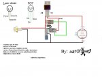
As far as volts, I suggest you supply 6v- 7v to a circuit like this...
As far as the 10ohm parallel this diagram should be similar to a real circuit you could make....
I think your trying to use a parallel of two 10 ohm .5 watt to obtain 5 ohm at 1 watt, not to obtain 10 ohm at .5 watt. Check the Ohms law for parallel resistors / series resistors to ensure your method obtains your goal.
SN
Attachments
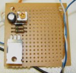
The image and the modified diagram are an attempt to line up the parts in a fashion to place them on a board and do the minimal of distant paths. If you place the parts in this fashion, there are only a few connections and no excess wires to use as the paths (not pre imprinted on the board) are local to one another. I like the arrangement, but of course you may not see things like I do and may prefer an alternate arrangement.
SN
SN
- Status
- Not open for further replies.
