- Joined
- Feb 5, 2008
- Messages
- 6,252
- Points
- 83
UPDATE !! !
PROJECT WORKS, SEE EDITS AND UPDATES BELOW!
OK folks, my 'delayed' regulator project... brought to finish.
I bought correct values of resistors, and after installing them instead of R3 and R8,
I was, again, frustrated by failure.
The summanabitch indicator light just kept lit no matter what I do.
Then it occured to me.
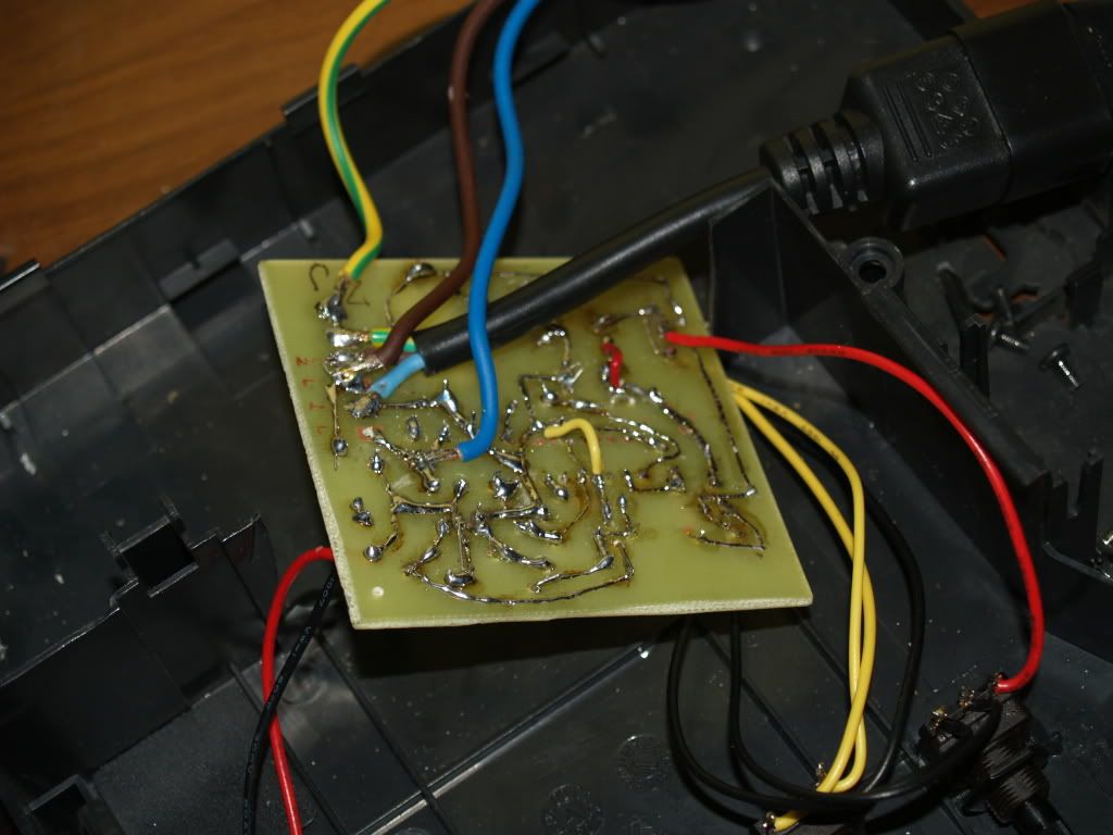
I quicly grabbed my ohmmeter, and went over the connections.
Guess what. Powerline with 220VAC was severd between the IC's pins it was supossed to connect.
Now, I tried it again. To my suprise, it began as it should: when power is switched on, the indicator light SHOULD NOT light, until the power usage of the soldering iron matched the value set by resistor marked GRUBo on schematic.
So, i turned the resistors around....
Again with no success. Starting to feel pesimistic?
Well, I thought maybe the first pair of resistors was OK, so i switched them again.
Same thing. Indicator light only blinks when power is supplied, and remains off whatever I do.
However this is where I noticed something.
Even though the light is off, the soldering iron is heating.
I grabbed my trusty 10$ meter, and measured the volts running into the iron.
There was standard 220 V AC on the input, however, there was 13 V AC over the iron
Yep, 13! Lucky number eh?
I thought, maybe it was the regulation process (iron was still hot from repairing the PCB) so I switched it off and let it cool off.
Turned it on and guess what. 13 V AC.
Took VERY long time to heat up.
I lost my nerves after many tries that day (yesterday, Sunday).
And I gave it up for that. So today, I managed to find the nerves to go try again. And guess what.
I find another severed line, between the row of resistors left from the PCB.
So, repaired that and let the iron cool off.
Turned it on again and again, 13V ac. HOWEVER, I unplugged my iron from the circuit and measured the voltage across the output.
181V ac.
Weird? That dig this: I plugged the iron back in and THEN it had 214 V ac across it. When it heated up, it was back to 13 V.
Twisting the post has no effect on the voltage again.
It seems the regulation is only halfway complete, when it is hot enough, it passes low voltage, but when it is cold again, it does not return the 220V on it.
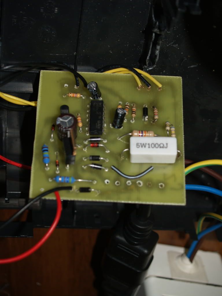
I am now officially looking for professionals' help, if you can judge from the pictures what the hell is wrong here, because I cannot belive that after that many repairs, tries and so on, it still won't listen to me.
Is it possible that the potenciometers from the original project had different pinout? Or whatever. All ideas are welcome :can: (except 'buy a soldering station' ones ofc)
So far, that means the iron heats up very quicly, and one it reaches the solder melting temperatire (a little above it acctually) it only remains at 13 Volts AC, just enough to keep it at that. If you ask me, it is somewhat OK, if I didn't put all the effort in it.
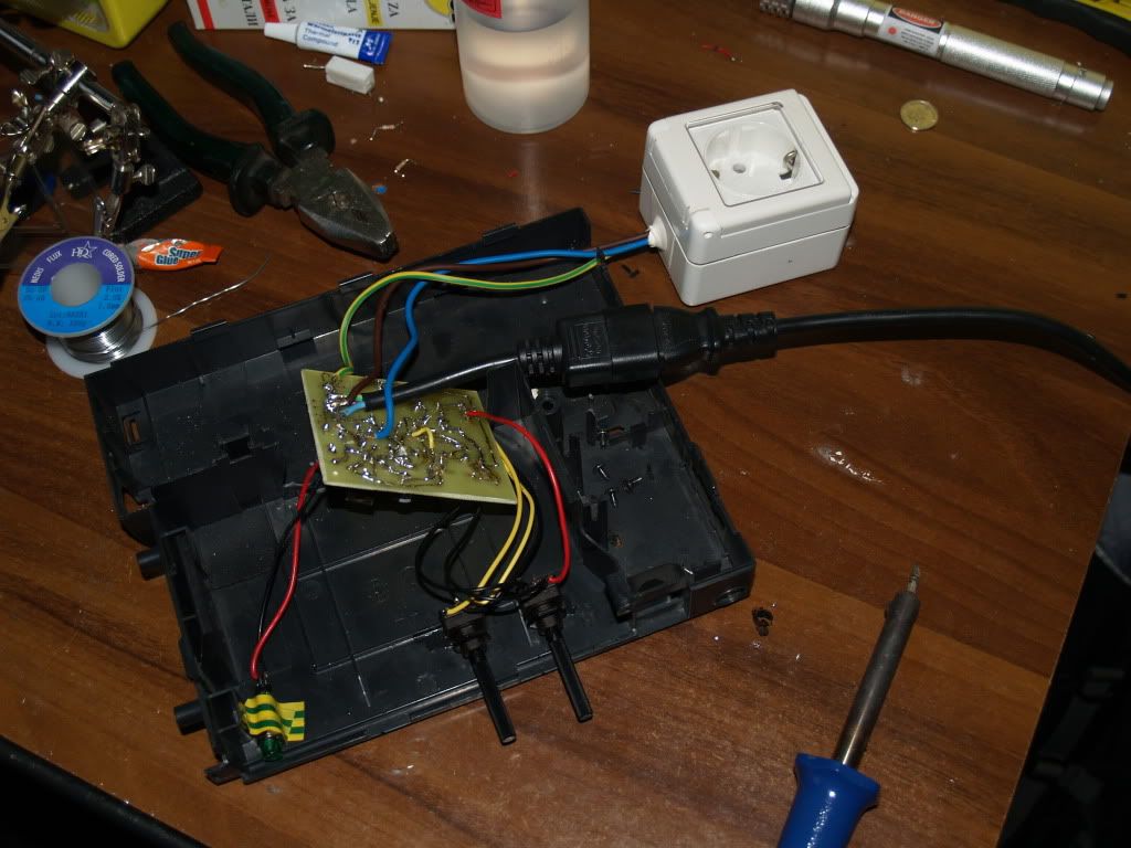
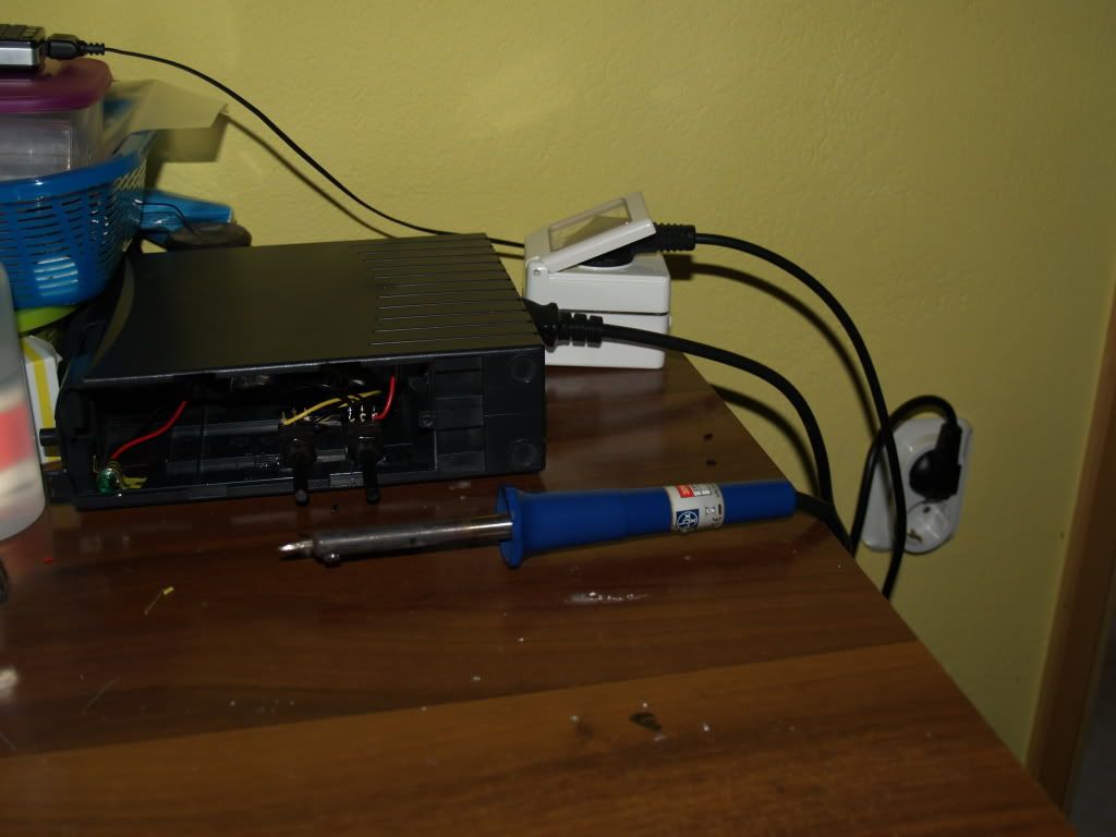
Well just in case there is no one that can figure it out, I'm still happy with auto voltage cutoff, and encased it all in a box earlier mentioned
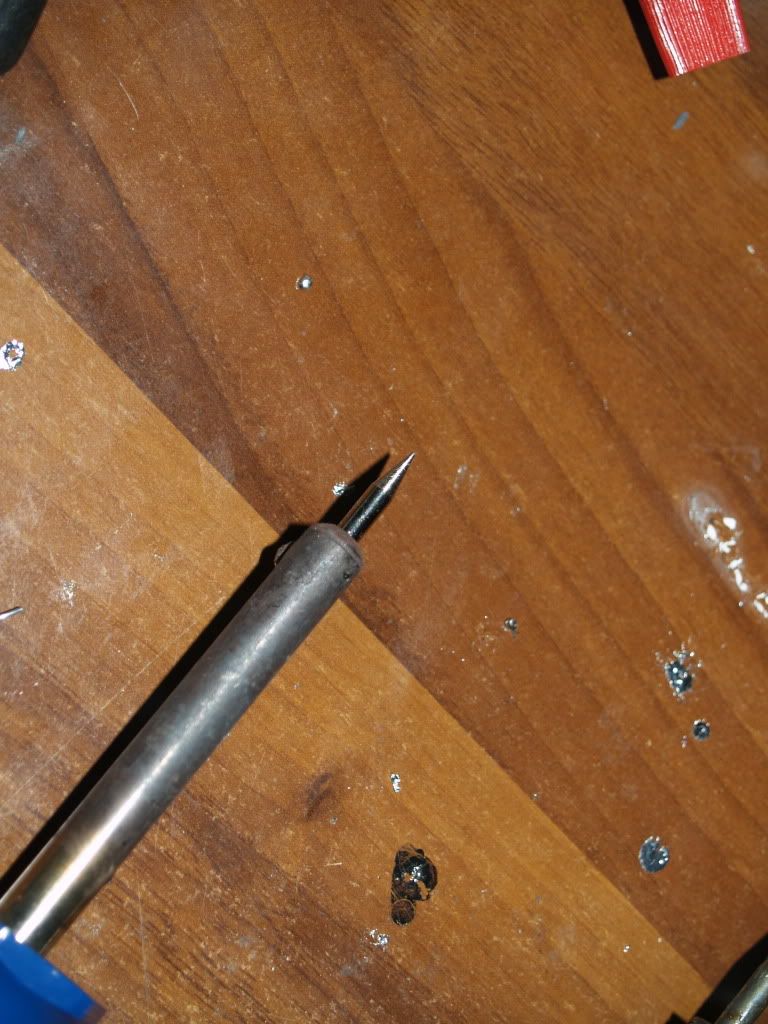
And just to add a finishing touch, replaced my very old soldering tip with brand new one.
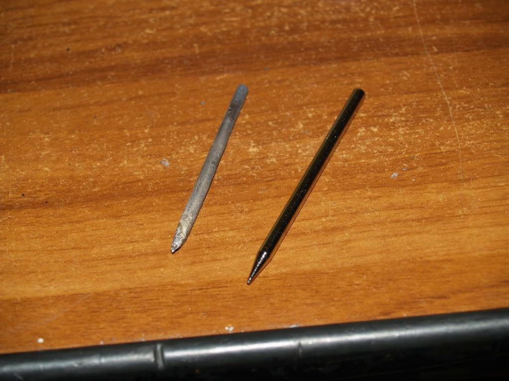
old one and new one uncomparable
PROJECT WORKS, SEE EDITS AND UPDATES BELOW!
OK folks, my 'delayed' regulator project... brought to finish.
I bought correct values of resistors, and after installing them instead of R3 and R8,
I was, again, frustrated by failure.
The summanabitch indicator light just kept lit no matter what I do.
Then it occured to me.
I quicly grabbed my ohmmeter, and went over the connections.
Guess what. Powerline with 220VAC was severd between the IC's pins it was supossed to connect.
Now, I tried it again. To my suprise, it began as it should: when power is switched on, the indicator light SHOULD NOT light, until the power usage of the soldering iron matched the value set by resistor marked GRUBo on schematic.
So, i turned the resistors around....
Again with no success. Starting to feel pesimistic?
Well, I thought maybe the first pair of resistors was OK, so i switched them again.
Same thing. Indicator light only blinks when power is supplied, and remains off whatever I do.
However this is where I noticed something.
Even though the light is off, the soldering iron is heating.
I grabbed my trusty 10$ meter, and measured the volts running into the iron.
There was standard 220 V AC on the input, however, there was 13 V AC over the iron
Yep, 13! Lucky number eh?
I thought, maybe it was the regulation process (iron was still hot from repairing the PCB) so I switched it off and let it cool off.
Turned it on and guess what. 13 V AC.
Took VERY long time to heat up.
I lost my nerves after many tries that day (yesterday, Sunday).
And I gave it up for that. So today, I managed to find the nerves to go try again. And guess what.
I find another severed line, between the row of resistors left from the PCB.
So, repaired that and let the iron cool off.
Turned it on again and again, 13V ac. HOWEVER, I unplugged my iron from the circuit and measured the voltage across the output.
181V ac.
Weird? That dig this: I plugged the iron back in and THEN it had 214 V ac across it. When it heated up, it was back to 13 V.
Twisting the post has no effect on the voltage again.
It seems the regulation is only halfway complete, when it is hot enough, it passes low voltage, but when it is cold again, it does not return the 220V on it.
I am now officially looking for professionals' help, if you can judge from the pictures what the hell is wrong here, because I cannot belive that after that many repairs, tries and so on, it still won't listen to me.
Is it possible that the potenciometers from the original project had different pinout? Or whatever. All ideas are welcome :can: (except 'buy a soldering station' ones ofc
)
So far, that means the iron heats up very quicly, and one it reaches the solder melting temperatire (a little above it acctually) it only remains at 13 Volts AC, just enough to keep it at that. If you ask me, it is somewhat OK, if I didn't put all the effort in it.
Well just in case there is no one that can figure it out, I'm still happy with auto voltage cutoff, and encased it all in a box earlier mentioned
And just to add a finishing touch, replaced my very old soldering tip with brand new one.
old one and new one
uncomparable
Last edited: