Welcome to Laser Pointer Forums - discuss green laser pointers, blue laser pointers, and all types of lasers

LPF Donation via Stripe | LPF Donation - Other Methods

Links below open in new window

ArcticMyst Security by Avery

---Bluray Open Can Pics---

jayrob

0
Joined
Sep 21, 2007
Messages
9,862
Points
113
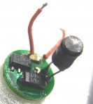
Nice looking host! That will be great for a blu-ray. Looks like you will need one of drlava's drivers if he has them available.
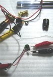
The LD case is grounded in it's original environment, so it won't hurt to ground the LD case if that's the way it gets mounted in your host/switch set up. But the negative side of the battery to the LD case will not make it light up. Take a close look at that link that I posted. I have a diagram there, as well as a link to drlava's picture of the pin connection...
Jay


JLSE

1
Joined
Dec 13, 2007
Messages
3,580
Points
0
For the 6x the power is a boost circuit @ 5.7v from 1.5v and a multi turn 100ohm pot. Im going to test the boost circuit at 3v in and see what happens. If the output goes up from 5.7 ive got mini 7805 5v reulators good up to 138ma @ 9v in. So ive got some work ahead.

What is the max voltage in for the BR's PS3 and 6x? Can they go up to 9v?
 

jayrob

0
Joined
Sep 21, 2007
Messages
9,862
Points
113
wannaburn said:
For the 6x the power is a boost circuit @ 5.7v from 1.5v and a multi turn 100ohm pot. Im going to test the boost circuit at 3v in and see what happens. If the output goes up from 5.7 ive got mini 7805 5v reulators good up to 138ma @ 9v in. So ive got some work ahead.

What is the max voltage in for the BR's  PS3 and 6x? Can they go up to 9v?

Someone else will have to jump in for that question. Because I have no knowledge about the boost circuits...yet. I have only been using the DDL style, LM317 based drivers. And as you probably know, with those drivers, all you have to worry about is the correct current. As long as you have at least 9 volts supply for the blu-ray builds...
Jay
 

JLSE

1
Joined
Dec 13, 2007
Messages
3,580
Points
0
I ordered a couple of led keychain 1xaaa lights. They have a tiny driver board which should do the trick.
So the diode should be getting 9v? They way ive been doing it with the ps3 sled is the 7805 which gives 5.4v and no problems.
But if 9v is the target, it make things less complicated :)
 

jayrob

0
Joined
Sep 21, 2007
Messages
9,862
Points
113
wannaburn said:
I ordered a couple of led keychain 1xaaa lights. They have a tiny driver board which should do the trick.
So the diode should be getting 9v? They way ive been doing it with the ps3 sled is the 7805 which gives 5.4v and no problems.
But if 9v is the target, it make things less complicated :)

I can tell you that the running voltage of the 6 X diode, will be the same as the PS3's. From 4.5 volts to 5 volts. 9 volts supply for a DDL style driver is needed because the driver will take about 3 volts or so, and the LD needs about 5.
I sure would like to learn more about the boost circuits. I have ordered 3 of BlueFusions boards. And I am hoping drlava will be soon making his lavadrive2 available...
Jay
 

JLSE

1
Joined
Dec 13, 2007
Messages
3,580
Points
0
jayrob said:
[quote author=wannaburn link=1207297517/15#19 date=1207547644]I ordered a couple of led keychain 1xaaa lights. They have a tiny driver board which should do the trick.
So the diode should be getting 9v? They way ive been doing it with the ps3 sled is the 7805 which gives 5.4v and no problems.
But if 9v is the target, it make things less complicated :)

I can tell you that the running voltage of the 6 X diode, will be the same as the PS3's. From 4.5 volts to 5 volts. 9 volts supply for a DDL style driver is needed because the driver will take about 3 volts or so, and the LD needs about 5.
I sure would like to learn more about the boost circuits. I have ordered 3 of BlueFusions boards. And I am hoping drlava will be soon making his lavadrive2 available...
Jay
[/quote]


These are the ones im using, there not too expensive, and arent much larger in diameter than a AAA battery. They zero my multimeter (over 400ma) and boost to 5.7. I still have to see what happens at 3v in, but have a good feeling ;)


http://cgi.ebay.com/ws/eBayISAPI.dl...item=230234197293&_trksid=p3984.cWON.m313.lVI
 

jayrob

0
Joined
Sep 21, 2007
Messages
9,862
Points
113
Looks like your taking the boost circuit driver out of that little light, and using it for your blu-ray build? That's very interesting! Please post pictures and details of your build after you do your testing and stuff...
Jay
 

JLSE

1
Joined
Dec 13, 2007
Messages
3,580
Points
0
I just tested the boost @ 3v 2xAA and surprisingly it doesnt heat up any, and maintains a steady voltage of 5.96v. The ony problem is @ 3v, it spikes to 13v. Is this going to be a problem? I use a cap in the circuit with all diodes, but ive never encoutered 13v! Below are some pics of the driver and meter testing at 3v.
 

Attachments

  • Untitled-1_004.jpg
    Untitled-1_004.jpg
    93.4 KB · Views: 94

JLSE

1
Joined
Dec 13, 2007
Messages
3,580
Points
0
Any idea what these parts on the board are? the cylindrical piece is a coil and what looks to me, a resistor across the output but im kinda lost on the other two :-/
 

jayrob

0
Joined
Sep 21, 2007
Messages
9,862
Points
113
I wish I could help you there, but I don't know about these circuits and components. You could PM drlava or rog8811 with this thread linked. Maybe BlueFusion or Hemlock Mike. I know that there are a few who may be able to help you out there. Gazoo is very helpful, but I have not seen his posts lately. He must be on vacation of something. I will be following this thread because I would like to learn more about this...
Jay
 

phenol

0
Joined
Oct 30, 2007
Messages
533
Points
18
the khaki rectangle whence the two red wires start looks like a ceramic capacitor. the round thing with radial leads is inductor, the SS14 component is a schottky diode , and the other black component with 3 terminals is probably the switching regulator. does it have any symbols on it?
 

JLSE

1
Joined
Dec 13, 2007
Messages
3,580
Points
0
The only thing is the numbers, which are as follows, 2100A 0627/45. Also the output spikes to 13v @ 3v in and 10v @ 1.5v in. I tried various caps, and havent been able to eliminate this spike. What is the best way to absorb these? 13v to the diode will surely be a bad thing. :(
 

phenol

0
Joined
Oct 30, 2007
Messages
533
Points
18
spiking would mean temporary short-lasting increase in voltage and subsequent settling to a lower value. it seems that the regulator is building up voltage as high as it can on whatever cap u place on its output. are you testing it without a load? it sure acts like a current source. place a 50 ohm resistor on its output as a load and see what happens....


Top