

D
Deleted member 8178
Guest
What you'll need:
- 1x Full Colour Driver Extension for the White Fusion kit (duh)
- 1x White Fusion Kit or other rgb/v set-up
- 1x 9-12V battery or power supply capable of the total load current
- fuse in series with your power source, capable of the total load current (optional)
- 1x on-off power switch capable of the total load current
- 2x momentary push buttons (program and option button)
- 3x TO220 insulation pads and bushings
- 3x size M3 nuts and bolts for the regulators
- ~2m wire
- shrink tube (optional)
- solder
- host
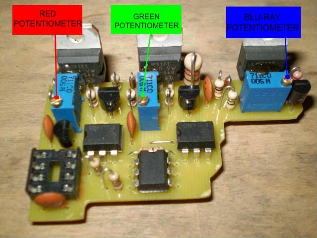
Driver overview:
1.
Measure the resistance of the sled with a DMM set to the conductivity setting (the one with a diode and buzzer symbol).
Between the green heat sink and sled: infinitive resistance (no buzzer)
Between the green heat sink and blu-ray heat sink: infinitive resistance (no buzzer)
Between the red heat sink and sled: 0 resistance (buzzer)
Between the blu-ray heat sink and sled: 0 resistance (buzzer)
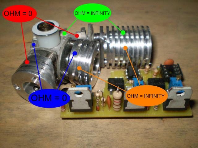
If you find any errors in these measurements make sure to fix it before proceeding. If everything is ok you can install the laser modules in the heat sinks (beware of the optical polarization), then repeat the testing just to be safe. The new white fusion kits seem to have a the red and blu heat sinks totally isolated from the sled and each other (i.e. infinitive resistance). Ignore this, it is not a problem. I advise to connect the case pin on the blu-ray diode to the negative pin.
2.
If you use the 695mA setting on the green laser, I highly recommend connecting two 1N4001 diodes in series with the module. Put the diodes on about half an inch length of wire from the module or directly on the output-terminals of the driver. This will make the forward voltage of the green module match the red and blue/violet laser, and will take some of the heat off of the driver.
Collect 12 pieces of wire (in different colours if you can) in 15-20 cm length and tin the ends.

Here are the location of the wire terminals. Solder with great care!
PWR + : Positive terminal from the battery
PWR - (GND) : Negative terminal from the battery
PR-B : Program button
PR-B (GND) : Program button
OP-B : Option button
OP-B (GND) : Option button
RLD + : Red laser diode positive pin
RLD - (GND) : Red laser diode negative pin
GLD + : Green laser diode positive pin
GLD - (GND) : laser diode negative pin
VLD + : Blue/violet laser diode positive pin
VLD - (GND) : Blue/violet laser diode negative pin
Here are all the wires in place:

Flipped over and the wire pairs twisted together:

Wire ID again, for those who ordered the driver with the wires installed:
3.
Lay out the driver, White Fusion kit, battery, buttons, and any another pieces you plan to use in your build, see how long the wires need to be, and just to see how it all fits together so you get a clear image in your head.
Keep in mind that:
Between the positive power wire and the positive battery terminal, you need to have an >1.5A on-off power switch.
If you choose to use an external power supply, make sure it is properly regulated with low ripple and 9-12 DC.
The regulators need to be heat sinked and electrically isolated from each other and ground, or any metal.
Make sure no metal is touching the driver anywhere.
The original green laser driver need to be removed.
Can you adjust your optical alignment easily with your set-up?
Ones you have it all figured out you can solder the wires to the battery terminals, power switch, buttons, and laser diodes, in that order. You shouldn't worry about any charge left in the driver, it has inbuilt bleeding resistors, but you can short the wires briefly before soldering the diodes just to be safe. And remember, the green laser is case positive.
4.
Double check everything.
5.
At this point you may put everything in your box, case, or whatever... and power it up for the first time. The regulators need to be heat sinked at all times when power is applied! Make sure that the power switch is off, then connect your batteries/power supply, then flip the switch.
You will now see that the red and violet lasers are glowing dim, the green might not glow at all (we get back to this later). This is idle lazing to make the blanking a little easier on the diodes.
Power off.
6.
Turn the potentiometers on the driver all the way counter clockwise, they are 25 turn...
7.
Take a look at this picture:
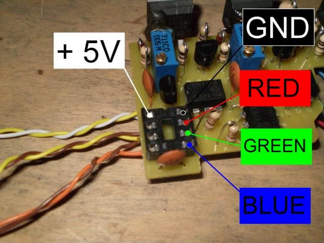
Now get a conductor (a resistor lead or similar)

Here you see it connected between +5V and red, this will activate the driver's red channel.
Leave it in and power it up again.
With the power on, turn the red laser's potentiometer clockwise till you get a good enough brightness to work with when you'll do the optical alignment (but not to bright! Concern your eyes!)

Repeat this for the green and blu.
Based on this, you can choose to modify your driver by adding 3 switches to make the standard 7-colour control. You can work both the IC and the 3 extra 7-colour switches independently totally safe. Just a neat little addition to your set-up.
8.
Make sure you turned off the power and get the IC:
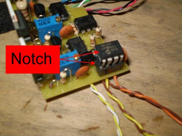
Push it all the way down.

Done.

9.
When you power it up this time, you see that the drives does it's colour changing thing...
Press both the program and option button at the same time briefly.
Then press the program button 31 times to get to the white marker in the list of programs.
10.
Now you can do the optical alignment while you're at the white marker.
11.
When that's done it is time for a little more power! :eg:
While still at the white marker turn all the potentiometers all the way clockwise. Then turn down the potentiometers to match the least bright laser (probably the blu-ray) and fiddle around till you get a good white balance.
12.
Yay, done.
Trouble shooting.
You may notice that the green module doesn't fade as smooth as the red and violet, it may even mode hop. That is typical for a DPSS-laser, but it might be some room for improvements...
Go to the black marker in the list of programs.
You see the red and violet glowing dim, but does the green? If it does glow slightly, all you can do is go to the rainbow program, and try to lower or increase the green laser's current and see if it gets more stable at some point. If that doesn't help I'm afraid you can't do anything more to make it better. If it is real bad you might just get a new, more stable module, but I doubt it will come to that.
But lets say it doesn't glow dim while at the black marker: I included an extra resistor (120 ohm, 1W) with the driver, try connecting it in parallel with the other 120 ohm resistor that is already on the driver to make a 60 ohm 2W resistor like this:

Then power up again and see if it glows dim while at the black marker. Even if it doesn't, still go to the rainbow program and see if it has improved.
If it hasn't improved you might experiment with some other resistor values between 40 and 120 ohm, 2-3W is recommended, don't use wire wound resistors.
If it glows too bright (you only want it to start to laze) while at the black marker, you need a higher resistance - but if it still mode-shifts very bad at this point all you can do is get a new, more stable module.
If adding the extra resistor haven't done any improvements what-so-ever, but you think the green is pretty descent anyway, take it off again because all it does it eat extra power.
Modification. Highly recommended.
There is one spot on the driver where you can drill a hole for a screw to secure the driver to the bottom of your case:

I suggest a 3mm hole.

Be careful not to damage the lead outside of the yellow line and avoid any electrical contact with it.
When your hole is done you should use a spacer between the driver and the bottom of the case, long enough to clear the wires and components under the driver freely and bolt it down tight.
And if you so choose you can add three switches for the standard 7 colour control:

This shows how you connect it. But you should solder the wires under the board of course.
The switches can be either an on/off or momentary push buttons, whichever you prefer. When one of the switches is activated the corresponding channel will be activated. So if you go the the black marker in the list of programs, you will have the 7 colours available via the switches. But you can also use them while running any other program, and you'll see how the pattern will change and make new effects!
Good luck! :yh:
- 1x Full Colour Driver Extension for the White Fusion kit (duh)
- 1x White Fusion Kit or other rgb/v set-up
- 1x 9-12V battery or power supply capable of the total load current
- fuse in series with your power source, capable of the total load current (optional)
- 1x on-off power switch capable of the total load current
- 2x momentary push buttons (program and option button)
- 3x TO220 insulation pads and bushings
- 3x size M3 nuts and bolts for the regulators
- ~2m wire
- shrink tube (optional)
- solder
- host
Driver overview:
1.
Measure the resistance of the sled with a DMM set to the conductivity setting (the one with a diode and buzzer symbol).
Between the green heat sink and sled: infinitive resistance (no buzzer)
Between the green heat sink and blu-ray heat sink: infinitive resistance (no buzzer)
Between the red heat sink and sled: 0 resistance (buzzer)
Between the blu-ray heat sink and sled: 0 resistance (buzzer)
If you find any errors in these measurements make sure to fix it before proceeding. If everything is ok you can install the laser modules in the heat sinks (beware of the optical polarization), then repeat the testing just to be safe. The new white fusion kits seem to have a the red and blu heat sinks totally isolated from the sled and each other (i.e. infinitive resistance). Ignore this, it is not a problem. I advise to connect the case pin on the blu-ray diode to the negative pin.
2.
If you use the 695mA setting on the green laser, I highly recommend connecting two 1N4001 diodes in series with the module. Put the diodes on about half an inch length of wire from the module or directly on the output-terminals of the driver. This will make the forward voltage of the green module match the red and blue/violet laser, and will take some of the heat off of the driver.
Collect 12 pieces of wire (in different colours if you can) in 15-20 cm length and tin the ends.
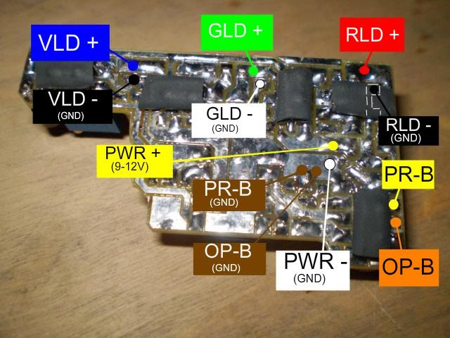
Here are the location of the wire terminals. Solder with great care!
PWR + : Positive terminal from the battery
PWR - (GND) : Negative terminal from the battery
PR-B : Program button
PR-B (GND) : Program button
OP-B : Option button
OP-B (GND) : Option button
RLD + : Red laser diode positive pin
RLD - (GND) : Red laser diode negative pin
GLD + : Green laser diode positive pin
GLD - (GND) : laser diode negative pin
VLD + : Blue/violet laser diode positive pin
VLD - (GND) : Blue/violet laser diode negative pin
Here are all the wires in place:
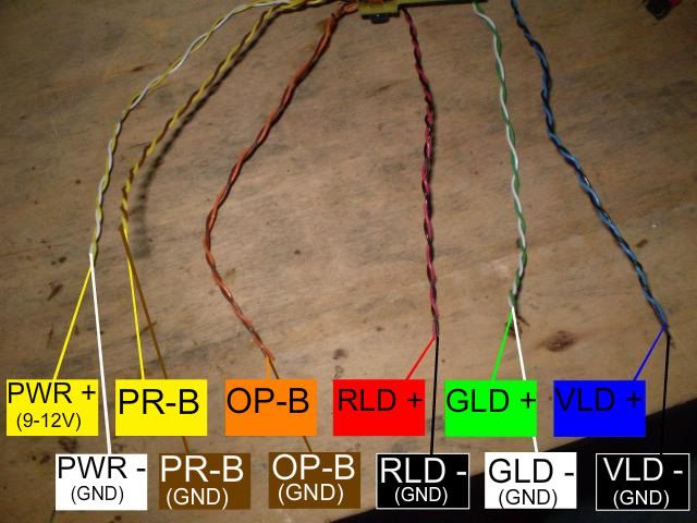
Flipped over and the wire pairs twisted together:
Wire ID again, for those who ordered the driver with the wires installed:
3.
Lay out the driver, White Fusion kit, battery, buttons, and any another pieces you plan to use in your build, see how long the wires need to be, and just to see how it all fits together so you get a clear image in your head.
Keep in mind that:
Between the positive power wire and the positive battery terminal, you need to have an >1.5A on-off power switch.
If you choose to use an external power supply, make sure it is properly regulated with low ripple and 9-12 DC.
The regulators need to be heat sinked and electrically isolated from each other and ground, or any metal.
Make sure no metal is touching the driver anywhere.
The original green laser driver need to be removed.
Can you adjust your optical alignment easily with your set-up?
Ones you have it all figured out you can solder the wires to the battery terminals, power switch, buttons, and laser diodes, in that order. You shouldn't worry about any charge left in the driver, it has inbuilt bleeding resistors, but you can short the wires briefly before soldering the diodes just to be safe. And remember, the green laser is case positive.
4.
Double check everything.
5.
At this point you may put everything in your box, case, or whatever... and power it up for the first time. The regulators need to be heat sinked at all times when power is applied! Make sure that the power switch is off, then connect your batteries/power supply, then flip the switch.
You will now see that the red and violet lasers are glowing dim, the green might not glow at all (we get back to this later). This is idle lazing to make the blanking a little easier on the diodes.
Power off.
6.
Turn the potentiometers on the driver all the way counter clockwise, they are 25 turn...
7.
Take a look at this picture:
Now get a conductor (a resistor lead or similar)
Here you see it connected between +5V and red, this will activate the driver's red channel.
Leave it in and power it up again.
With the power on, turn the red laser's potentiometer clockwise till you get a good enough brightness to work with when you'll do the optical alignment (but not to bright! Concern your eyes!)
Repeat this for the green and blu.
Based on this, you can choose to modify your driver by adding 3 switches to make the standard 7-colour control. You can work both the IC and the 3 extra 7-colour switches independently totally safe. Just a neat little addition to your set-up.
8.
Make sure you turned off the power and get the IC:
Push it all the way down.
Done.
9.
When you power it up this time, you see that the drives does it's colour changing thing...
Press both the program and option button at the same time briefly.
Then press the program button 31 times to get to the white marker in the list of programs.
10.
Now you can do the optical alignment while you're at the white marker.
11.
When that's done it is time for a little more power! :eg:
While still at the white marker turn all the potentiometers all the way clockwise. Then turn down the potentiometers to match the least bright laser (probably the blu-ray) and fiddle around till you get a good white balance.
12.
Yay, done.
Trouble shooting.
You may notice that the green module doesn't fade as smooth as the red and violet, it may even mode hop. That is typical for a DPSS-laser, but it might be some room for improvements...
Go to the black marker in the list of programs.
You see the red and violet glowing dim, but does the green? If it does glow slightly, all you can do is go to the rainbow program, and try to lower or increase the green laser's current and see if it gets more stable at some point. If that doesn't help I'm afraid you can't do anything more to make it better. If it is real bad you might just get a new, more stable module, but I doubt it will come to that.
But lets say it doesn't glow dim while at the black marker: I included an extra resistor (120 ohm, 1W) with the driver, try connecting it in parallel with the other 120 ohm resistor that is already on the driver to make a 60 ohm 2W resistor like this:
Then power up again and see if it glows dim while at the black marker. Even if it doesn't, still go to the rainbow program and see if it has improved.
If it hasn't improved you might experiment with some other resistor values between 40 and 120 ohm, 2-3W is recommended, don't use wire wound resistors.
If it glows too bright (you only want it to start to laze) while at the black marker, you need a higher resistance - but if it still mode-shifts very bad at this point all you can do is get a new, more stable module.
If adding the extra resistor haven't done any improvements what-so-ever, but you think the green is pretty descent anyway, take it off again because all it does it eat extra power.
Modification. Highly recommended.
There is one spot on the driver where you can drill a hole for a screw to secure the driver to the bottom of your case:
I suggest a 3mm hole.
Be careful not to damage the lead outside of the yellow line and avoid any electrical contact with it.
When your hole is done you should use a spacer between the driver and the bottom of the case, long enough to clear the wires and components under the driver freely and bolt it down tight.
And if you so choose you can add three switches for the standard 7 colour control:
This shows how you connect it. But you should solder the wires under the board of course.
The switches can be either an on/off or momentary push buttons, whichever you prefer. When one of the switches is activated the corresponding channel will be activated. So if you go the the black marker in the list of programs, you will have the 7 colours available via the switches. But you can also use them while running any other program, and you'll see how the pattern will change and make new effects!
Good luck! :yh:
Last edited by a moderator:


")
 I wana see it.