Driver 90% scoped.
I scoped The drive as photo'd with my lead inverted and sure enough the output to the GDT measures 4.5 kHz. With a square wave. @ a hair over 12v
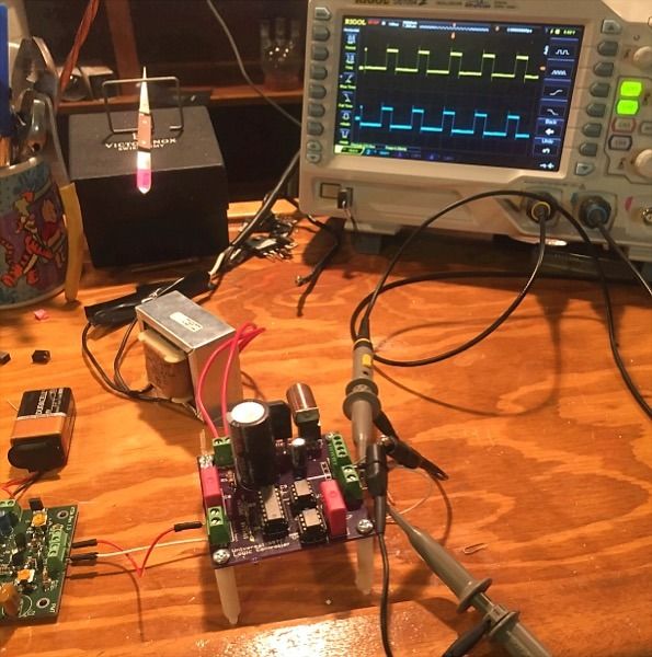
Next I hooked up the probes to the two ICs pins 7 and the neg rail WITHOUT inverting one channel and got a similar waveform. (I'll spare you the duplicate photo but they were the same)
Last 10% are you referring to the 14dip Ic as the Schmidt trigger? Are these steps in reference to ground or neg rail? vv
Quote:
"2) Same square wave at pin 1 of the schmidt trigger IC
3) 12V square wave at pin 4 of the schmidt trigger and pin 2 of the UCCs"
Looks like the driver is working fine.
Next maybe its back to the drawing board on the GDT(15T) and bridge. All the parts are new and should work.


")


