Welcome to Laser Pointer Forums - discuss green laser pointers, blue laser pointers, and all types of lasers

LPF Donation via Stripe | LPF Donation - Other Methods

Links below open in new window

ArcticMyst Security by Avery

Re boarding a DXtrue 100

IgorT

0
Joined
Oct 24, 2007
Messages
4,177
Points
0
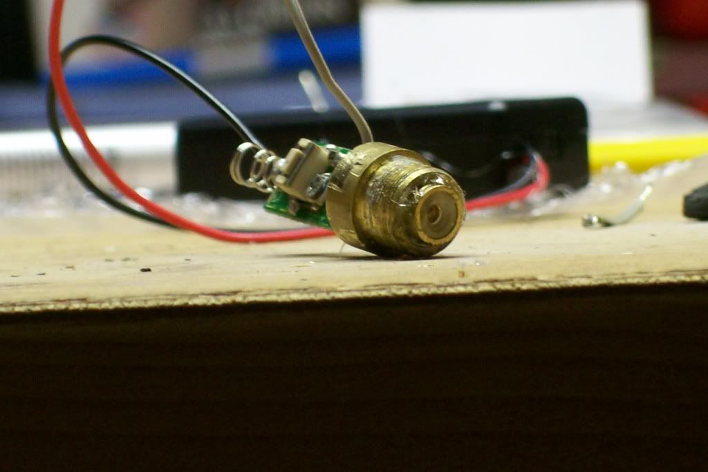
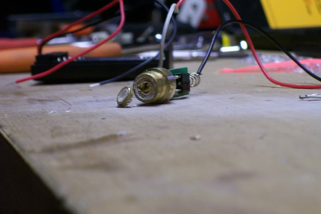
A glass AixiZ lens might not provide the required adjustability, because it has a metal collar, so you can not screw it in very deep..

Oh, and i noticed, that if the beam is not expanded enough, it is impossible to narrow it down from a certain spot size.. There is nothing you can do at all. I'm gonna have to find a different expander lense position, to get a smaller divergence.


The less expanded the beam, the less effect the collimator lens has. The only thing that bothers me is, that the expander lens is not easily adjustable, because it's only held there by glue.

That, and the fact, that i won't be able to work on my laser before the beginning of next week, because of too much work. :)


Joined
Sep 12, 2007
Messages
712
Points
0
yea i herd the glass aixiz lens u get from ebay has a plastic collar, not sure tho i haven't gotten one myself yet.

and wow!! the head is on there good! i have it clamped down into a huge vice and im heating it with a soldering iron.
eh i'm not sure how i can do this. im pulling on the rest of the laser as much as i can but nothing
am i supposed to use this much force?
 

IgorT

0
Joined
Oct 24, 2007
Messages
4,177
Points
0
pwnstar said:
yea i herd the glass aixiz lens u get from ebay has a plastic collar, not sure tho i haven't gotten one myself yet.
I meant the glass AixiZ lens in the metal nut.. That one has a metal ring, so you can't screw it in deeper than to the ring..

And since the AixiZ lenses are much more powerfull, than the one inside the laser, you might need to bring it in further, or at least adjust the unadjustable expander lens.. :)


Besides, if you are happy with your divergence, you might want to leave the two lenses glued in place.


You might have to take off the expander lense, if you'll have to get to the crystals. But this one will be "fun" putting back, as there is nothing to hold it there, but blobs of glue.. No threads or anything.. I've never seen such a thing..


It might be better to only try rotating the diode first, before doing anything to the crystals. Mark their diagonals from below, when you take the diode out, and align the chip with one of them and tighten the nut to test. Do not test with a loose diode, or you can kill it, or at least shorten it's life dramatically!


and wow!! the head is on there good! i have it clamped down into a huge vice and im heating it with a soldering iron.
eh i'm not sure how i can do this. im pulling on the rest of the laser as much as i can but nothing
am i supposed to use this much force?
I'm afraid you have to use even more...

I damaged the finish on the head this way.. I held it in pliars through a piece of cardboard (to keep it safe) but it was slipping.. So i taped it in electrical tape and grabbed with pliars again, and didn't even notice, when their teeth went through the tape and the silver finish..


After that i heated it with a lighter, while holding it so, that the smoke wouldn't go in (better to tape it down), and edged it out.


As i said, pulling in the "out" direction, doesn't help. Twisting kills the LD.

You have to edge it out. The head has to be held as firmly as possible, while you push and pull at 90°, at the same time as up. :) I don't know, how to put it in words any better..


When i did this, i finally noticed, that it is coming out by fractions of a milimeter.. Once you do that, it becomes easy.. You just keep edgeing it out.

No twisting or unscrewing, or you lose the IR! Since the PCB is only held by the LD's legs, and also prevented from turning by the button, it would stay in place during twisting, and the legs of the diode would get ripped off.

I've seen a couple of pictures somewhere aroung here, of people, who did that..
 
Joined
Sep 12, 2007
Messages
712
Points
0
You have to edge it out. The head has to be held as firmly as possible, while you push and pull at 90°, at the same time as up. :) I don't know, how to put it in words any better..

omg i get it, and i just got it!
yea the 90° thing helped thanks alot!
now i have to look inside...
ill give another update in a bit, but it looks good so far

Edit:
seems like the spring is loose that gets the positive charge from the battery's.
im trying to solder that back on at the moment...
anyway im not getting any green light now but i can see the IR from my ir-webcam.
im goin to start to rotate the diode and ill post sum pics in a little bit
=P =P =P
 

IgorT

0
Joined
Oct 24, 2007
Messages
4,177
Points
0
That's good.. Mark the diagonals of the crystal on the underside of the module, then mark the wider part of the chip on the underside of the diode, and align the lines.

This should give you the best results.


BTW: I think mine is fixed!!! :) I just tested it again, and it seems to work great! It lights a match very fast.

Maybe it's not exactly as bright as it was originally - can't verify untill i get the second one or the meter - but the mode hopping is gone completelly!


It took me a week of fiddling, and frustration, but it was worth it! It would take aligning in front of a meter, to get it any better than it is at the moment, so it'll just have to wait untill i get all the parts. The last few mW are the hardest to get out.. Especially with threads as loose as this..

If only the threads were a little finer, the fine tuning could actually be fine..
 
Joined
Sep 12, 2007
Messages
712
Points
0
im glad to hear urs works! :D
gives me more motivation

i think im going to put sum thermal compound on the threads so there not as loose.
are u planing on adding a ir filter to urs?

and here's my laser...
100_0879.jpg

100_0881.jpg

100_0882.jpg

100_0883.jpg
 

IgorT

0
Joined
Oct 24, 2007
Messages
4,177
Points
0
I see you also damaged the head.. Is it just the paint or did it go into the brass? I made quite deep scratches in the brass, and it took me an hour, to polish them out. I'll repaint it when i'm done, because brass doesn't look good when it oxidises...

I see you left the brass piece which also holds the collimator lens on the lower part of the module.. You can take if off, to see the expander lens, but don't take the expander off just yet, unless you're sure, you can't fix your laser just by turning the diode alone. Unfortunatelly, removing the expander is the only way to get to the crystals.

But i would like to see a picture of the expander lens. Some are glued directly on top of the lower module (diode and crystals), but mine was held up, like 1.5mm above the module.


Do not power the diode, unless it's tightened into the lower part of the module. And if you leave the larger part of the module on as well (like you did), it provides additional heatsinking during testing.


You're gonna have to be very patient tho. Since you can not turn the diode with the power on (at least not safelly), you're gonna have to align the fast axis with the diagonal perfectly before you tighten the nut, and be very carefull, that tightening doesn't rotate the diode a bit..


To get the final few mW out of the laser it might be necessary to turn the crystals as well tho.. I'm gonna make a pic of the tool i made for turning them with the power on.

Unfortunatelly i have to find it first.. I managed to lose it somehow.. I had a few very busy days and made a huge mess in my office/workshop.
 

IgorT

0
Joined
Oct 24, 2007
Messages
4,177
Points
0
What happened to your pics?

I just made a pic of my crystal aligning tool. I made it out of a small flat piece of alluminum, by cutting out the shape with scissors, and bending it to this shape.

It fits tightly onto the threads, but can easily be turned. The bent part, that goes in never touches the crystals, and is just wide enough, to fit into the opening of the crystal nut.


Without it, i could never have fixed the laser, since it would be impossible to turn the crystals with the power on.
 

Attachments

  • AligningTool.JPG
    AligningTool.JPG
    47 KB · Views: 89
Joined
Sep 12, 2007
Messages
712
Points
0
yea srry fixed the pics
that looks usefull,
rotating the diode is hard, i got green for a bit but couldn't get it back after i put the laser down. i should probably have my hot glue ready in case i find a sweet spot. i just put sum thermal compound on the treads its makes it not be as loose when ur trying to rotate it. im hopeing i can rotate the diode to fix it but maybe not
probably by tomorrow ill take a look at the crystals and try to make that tool.
i really cant w8 to see green again! =P
 
Joined
Sep 12, 2007
Messages
712
Points
0
ill try to take a pic of the expander lens tonight and get it on here
it seems like i have to move the crystals....
 

IgorT

0
Joined
Oct 24, 2007
Messages
4,177
Points
0
pwnstar said:
ill try to take a pic of the expander lens tonight and get it on here
it seems like i have to move the crystals....

Yeah, unfortunatelly you can't really finetune the rotation of the LD, while you can do it with the crystals.

Just be carefull, when breaking the glue bond. You wouldn't want to hit them with anything. This is the harderst part. After that you just have to clean the glue out completelly.


I'm looking forward to seeing how the expander is mounted on yours.. Could you tell me, what the divergence was, when it was still good?


Oh, if you look at the pic with the tool, those red lines are what i have to align the diagonal of the crystals with, or when i turn the diode, what i have to align the fast axis with.

I carefully screwed the crystals in, untill they almost touched the LD, went back just a little (so i could still adjust both ways if necesary), and marked the corners of the crystals. It made my job a lot easier..

From what i can tell, they have to be as close as possible, with the diagonal aligned with the fast axis, to get the most IR in, and the most green out. I also noticed, that when the alignment is good, the IR leaking goes down so much, that it's not noticable anymore on a camera.


Once you have the expander off, you will be able to see mode hopping in much more detail. Some of the patterns are crazy. This should make it easyer to find the sweet spot.


If you have any good ideas of how to mount the expander back on later, please share.


Good luck!
 
Joined
Sep 12, 2007
Messages
712
Points
0
maybe nail polish to put the expander back on or a very small amount of hot glue.

i still need to scape all that junk glue off...
i don't know the mrad # but the divergence on my laser was very good almost comparable to aixis lens on my DYI red about 100 feet away.

im goin to try to make that adjustment tool out of a soda can.
im getting started on that now.

here is the messy expander lens

100_0892.jpg

100_0901.jpg

100_0896.jpg

100_0902.jpg
 

IgorT

0
Joined
Oct 24, 2007
Messages
4,177
Points
0
I see your expander was sitting directly on the module.. That's not gonna be hard to glue back precisely.

In mine the expander was held 1.5mm above the module with four drops of epoxy.. That will be slightly harder to reproduce.. If it's not perfectly horizontal, the beam might not hit the collimator fully.

Also, since the only way to make divergence any better is to change the distance of the expander, i would be much happier, if the expander was threaded, and had somewhere to be screwed in for easy adjustment..


Since your expander is sitting directly on the module, your crystals are much closer to the IR, which is the way it should be.. You should try only very small adjustments around that position.

Under a strong light, you can see the IR chip through the crystals, which makes aligning the diagonal with the wide part of the chip (fast axis) much easier.


Good luck! I really hope you can bring it back to life.

If everything works out at the customs, i'm getting my second one tomorrow. I really hope it's better this time.
 

IgorT

0
Joined
Oct 24, 2007
Messages
4,177
Points
0
Well, i got the second one yesturday, and it is not very good... It only mode hops with completelly full batteries, when it gets very hot, but even when it doesn't mode hop, it has abrupt brightness changes.

With current regulation, i could prevent the mode hopping, especially if i improoved the heatsinking, but i don't want to risk it. I'm returning it.


Now i will continue realigning the first one. I need to mount the module in a vice, to provide some heatsinking. Otherwise, it heats up too much, which can shorten the life of the diode, and the results would not be the same as with the assembled module..


I suggest you mount it in a vice as well. Without heatsinking it is impossible to find a decent alignment.
 

IgorT

0
Joined
Oct 24, 2007
Messages
4,177
Points
0
Mounting it in a vice definatelly helps with finding the sweet spot! Before it would only get bright for a moment and immediatelly drop or modehop because of heat. Now it stays cool.

I managed to find four very bright alignments this way (all at 90° from each other - diagonals of the crystal and as close as possible to the diode without touching it). One of them the brightest.

Now i just have to return to it and make very small changes, till i get as much power out as possible. After that it gets better heatsinking in a very massive body. I'll swap the bodies with the KD50 (the modules are almost identical) and replace the driver. It could turn into a great laser when i'm done...


The driver is going to be two AMCs, so it can work from a single Li-Po. Maybe with a bypass resistor, to reduce the current to 600mA.


I'm also making an add-on driver for unmodified DX lasers. It will be the size of an AAA battery, and will slide into the battery compartment together with an AAA size Li-Po (10440), and keep the current constant.
 
Joined
Sep 12, 2007
Messages
712
Points
0
hmm the heat changeing the brighness explains alot...
i did get green again! but i couldnt get it back after it probably cooled down.

I'm also making an add-on driver for unmodified DX lasers. It will be the size of an AAA battery, and will slide into the battery compartment together with an AAA size Li-Po (10440), and keep the current constant.

that sounds like a good idea. what would your add-on driver regulate.


Top