Welcome to Laser Pointer Forums - discuss green laser pointers, blue laser pointers, and all types of lasers

LPF Donation via Stripe | LPF Donation - Other Methods

Links below open in new window

ArcticMyst Security by Avery

Question about 808nm ir build


anselm

0
Joined
Nov 22, 2010
Messages
2,448
Points
0
1st driver doesn't look too bad, second one I wouldn't buy that.
Instead get a 7$ greenie pen, inside you will find a driver just like that or very similar.
Plus you get to keep the DPSS and host.

Solder each pin of the diode to the corresponding tab on the driver, be careful not to break the pins when you can't avoid to bend them..
Battery - to the spring, battery + to the diodes case.
The spring on the odicforce would go on the "switched V-", unless you'd want to use your own (external) switch.
 
Last edited:

Machro

0
Joined
Nov 14, 2010
Messages
208
Points
18
Thanks. Now I want around 250mw from these common 5.6mm 300mw from ebay. Could you recommend a current setting ?
 

Machro

0
Joined
Nov 14, 2010
Messages
208
Points
18
So is there anybody dealed with these diodes before ? I need advice please
 

anselm

0
Joined
Nov 22, 2010
Messages
2,448
Points
0
Well if you have all the info about the diode, why not just use those values?
You can always up the current later on when you feel comfortable, you know
people here routinely drive all kinds of diodes at 150-200% of the suggested operating current.:whistle:
 
Last edited:

Machro

0
Joined
Nov 14, 2010
Messages
208
Points
18
Solder each pin of the diode to the corresponding tab on the driver, be careful not to break the pins when you can't avoid to bend them..
Battery - to the spring, battery + to the diodes case.
The spring on the odicforce would go on the "switched V-", unless you'd want to use your own (external) switch.

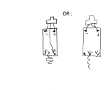
Just read the description again and it says the V+ input is already connected to the LD+ , so do I still have to solder a wire , or can I just bend the case pin to the LD+ ?
 

Machro

0
Joined
Nov 14, 2010
Messages
208
Points
18
THIS may better explain my question :crackup:
 

Attachments

  • Laser.png
    Laser.png
    13.9 KB · Views: 538

anselm

0
Joined
Nov 22, 2010
Messages
2,448
Points
0
I don't understand your drawing at all.
What driver are you using after all? The odic-force?
Well I never used one of those before so I can only guess.

Also, your picture looks wrong to me, because the case pin is the anode,
the pin conterclockwise form the case pin is the cathode, and the pin opposite
the cathode is unused....

Is this going to be a pointer or a labby.
I mean is it an issue in your case that the diodes case pin is positive?


Top