Welcome to Laser Pointer Forums - discuss green laser pointers, blue laser pointers, and all types of lasers

LPF Donation via Stripe | LPF Donation - Other Methods

Links below open in new window

ArcticMyst Security by Avery

Newbie needs help!

Joined
Aug 9, 2011
Messages
9
Points
0
Hi everyone,

I am very much new to lasers, and am attempting to build a 3D laser scanner using a laser line module I purchased and the David Laser Scanner tutorial.

My question is simple: how do I power the laser? The spec sheet states the Operating Voltage is 4.5V DC, and the Operating Current is 30mA. It is a 650nm, 5mW laser line module.

I was able to power the laser using 3 AA batteries, but was wondering two things:

1) is this safe and economical? (i.e. will I burn the laser, and how long will the batteries last)

2) what is the best way to go about putting together a power supply?

I have spent a lot of time reading different threads and tutorials, and have tried to learn about drivers, diodes, voltage regulators, etc. I am still very much confused about the role of each of these in powering a laser.

I am also wondering if I could use a wall charger from another device, one rated at 5V for example, but whose current is more than 30mA...say 50 or 100mA.

If anyone can help (even if it is links to tutorials or more information I should be reading) I would really appreciate it.

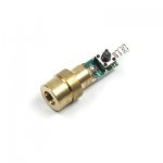
I have attached a picture of the laser module for reference.
 

Attachments

  • 319ky4EM7oL._SS400_.jpg
    319ky4EM7oL._SS400_.jpg
    7.9 KB · Views: 200
Last edited:


ARG

0
Joined
Feb 27, 2011
Messages
6,772
Points
113
Batteries are a safe way to power it, for a power supply, I would use 5V a wall wort.
 
Joined
Nov 18, 2009
Messages
269
Points
0
Above post is correct!

when it comes to wall AC/DC converters (as u called charger) the rated mA on the converter is the maximum amperage it will be able to deliver at the said voltage, not what it is going to really give to your circuit.

And as the photo clearly shows a driver, its completely fine to use the 5V converter, as the driver will make your "charger" deliver the laser diode's rated current.

have fun and welcome to the forums

EDIT:
For safety reasons, first connect ur converter to a dummy load (or only for a few seconds to your laser) in order to verify if with a load it really delivers 5V. sometimes those wall converters say 5V and in fact they are outputing much higher voltages even with loads. I dunno how the driver on that laser works, but i wouldnt want to risk 9V on it...

2nd edit: when it comes to powering up a laser diode (not a green laser, those are a bit different), u need to have ur current maxed to a certain value, e.g. have it so that it never goes over a certain limit. Why is that? Laser diodes work with electrons...as electrons pass right in the middle of the laser diode they do a quantum jump and emit your laser light. As you might know, current is electrons per second, so, the more current u have, the more electrons are passing in the muiddle and more light is being generated. this is also the same principle of LEDs...difference is in lasers you need a sort of optical feedback that will amplify your light in a coherent way, so, in order to get this, you need mirrors, but they still let pass some light (in the case of diodes it reflects around 30% and lets 70% get through). so in a laser diode, u got mirrors in both ends, and if u pump with too much current, the mirrors arent able to get enough light out and as the light gets too high, they get damaged and your laser turns a LED because you no longer have a way to amplify ur light. Now when it comes to voltage, it is simply a gate. when u apply a certain voltage, then current is allowed to go through...if u dont give enough voltage, current cannot go through the laser diode, and that's its role.

Hope i cleared whats the role of current and voltage on this precious diodes! :D
 
Last edited:
Joined
Sep 24, 2010
Messages
1,364
Points
0
If i was you i just connect it to 3 x 1.5 volt aa batt, scanning doesn't take that long does it ?
 
Last edited:
Joined
Aug 9, 2011
Messages
9
Points
0
Batteries are a safe way to power it, for a power supply, I would use 5V a wall wort.

Thanks for the help! I first tried using the 5V adapter that I have, and the laser would not turn on.

When I stripped the charger wire, I found a wire wrapped around another (white) casing with a wire running inside. I read in a few places that the double-insulated wire (white) is negative, and the wire wrapped around is the positive.

I connected these wires to the laser as indicated in the spec sheet, and nothing. I then tried switching the wires, and victory!

@LordKaramazov:

Thanks for your input! So the laser module I have has a built-in driver, whose purpose is to regulate the amperage? Does the driver serve another purpose?

Also, if there was no driver, what options would I have in terms of a power supply?

One reason I wanted to use a charger (or AC/DC converter I guess) is that I could not get the batteries to stay connected together. I put 3 AA batteries in series, and used electrical tape to hold them together, and then connected one wire to the (-) end and then to the laser, and another wire from the (+) and then to the laser.

When I did this, the laser would not turn on until I applied some pressure to either end of the batteries; it appears that the connection between the batteries was not tight enough.

I am going to use the wall charger for now, and attempt to put together a case for the laser in which I could use batteries to power it...makes it slightly more portable.

Again, thanks for your help guys. I hope my questions are not too simplistic for you!
 
Joined
Nov 18, 2009
Messages
269
Points
0
So the laser module I have has a built-in driver, whose purpose is to regulate the amperage? Does the driver serve another purpose?

I re-edited my first post (im at "work" and i didnt finish it the first time). Your driver is there to ensure the voltage given to the diode is the correct one, as also the current. Normally, those drivers are able to give any voltage (within a certain range of course...lets just say any voltage as its no problem here). how does it work? the driver feeds the laser with a certain current, and as the laser wants to work with that current the laser will "request" the driver to give him the appropriate voltage to have its "gate" open, the driver then gets the appropriate voltage. and most probably it has also polarity protection. that means that it will save ur diode and ur circuit in case u connect the + and - in the wrong way. and thats the role of the driver.

Also, if there was no driver, what options would I have in terms of a power supply?

If u have one of those Laboratory regulated voltage/current units, then u can set it to 30mA and 4.5V and use it. If u dont, either you would have to build your own driver, or order one from someone...never connect a laser diode directly to either batteries or a converter. (btw, the driver is the circuit attached to the laser)
 
Last edited:
Joined
Sep 12, 2007
Messages
9,399
Points
113
It looks to me like the "driver" is a simple current limiting resistor. If this is the case, a 5V wall adapter will only work at the rated current if you drop the voltage. A 17 ohm resistor (or nearest match) should do the job.
 
Joined
Nov 18, 2009
Messages
269
Points
0
Oh! hadnt looked to the pic in big, only the thumbnail.

now that cyparagon mentioned it, and i saw the pic, yeah, its a very simple driver u got there, it wont have polarity protection...as u connected the wires wrongly there was no prob because it was a small voltage...

do like he (Cyparagon) says if using higher voltage (in this case the 5V)
 
Joined
Aug 9, 2011
Messages
9
Points
0
It looks to me like the "driver" is a simple current limiting resistor. If this is the case, a 5V wall adapter will only work at the rated current if you drop the voltage. A 17 ohm resistor (or nearest match) should do the job.

How would I go about connecting a resistor to the wall adapter?
 
Joined
Aug 9, 2011
Messages
9
Points
0
I connected the laser to 3AAA batteries in a battery holder, and the laser turned on and stayed on for approximately 2 minutes before the batteries dying out.

I then went back to the wall adapter, but connecting it directly would keep making the laser module very hot within a few seconds.

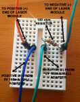
My next option was to use a solderless breadboard to try to figure out how to apply the resistor. The smallest resistor I had was 100 ohms, and the wiring was done as the pics below.

Even with this setup, the laser turns on, but gets extremely hot within a few seconds. I did not notice any difference in the laser intensity with and without the resistor (so I assume I've set up the wires incorrectly).

I must admit that searching and reading has been very little help, as most of the posts on this forum assume a great deal of background knowledge in circuits and electronics. Even threads for so-called "newbs" include complex circuitry and terminology that goes unexplained.

I hope someone can help me with this! Thanks.
 

Attachments

  • breadboard.png
    breadboard.png
    490.4 KB · Views: 242
  • module.png
    module.png
    546.6 KB · Views: 207
Last edited:
Joined
Sep 22, 2010
Messages
1,358
Points
48
Hmm. Could he simply use a 1N4401 diode to drop the current to ~4.3v? I guess it'd depend on the input tolerance of that driver but I'd suspect it'd run fine on 4.3v.
 

ARG

0
Joined
Feb 27, 2011
Messages
6,772
Points
113
breadboard.png

Not sure about your breadboard, but mine is connected in strips horizontally, so it may not be going through the resistor.
 
Joined
Sep 22, 2010
Messages
1,358
Points
48
Good catch. It's likely bypassing the resistor all together. I'd move the right side up a row or two.
 
Joined
Aug 9, 2011
Messages
9
Points
0
Hi guys,

Thanks to all of you for your replies and the help you've provided.

I decided to put together a driver for the for my laser diodes, but am running into a problem with the voltage.

I've put together the DDL driver as described in the original thread, using the LM317T, a 47 uF capacitor, and a 1N4001 diode. I left out the potentiometer for now as I'm more concerned about the voltage than the current (the original current from the charger was hovering around 250mA, and I added a 33 ohm resistor which dropped the current down to around 35mA, which is the rating of my laser).

I've connected a 9V battery (and later a 5V wall charger) to the protoboard, and each time, the output voltage (measured with a multimeter at the green (+) and orange (-) wires in the picture) is around 8.6V with the 9V battery and 4.72V with the 5V charger.

From the DDL schematics and explanations, I was under the impression that the LM317T would output around 4.5V from a 9V battery. What am I doing wrong here?
 

Attachments

  • proto.png
    proto.png
    559.1 KB · Views: 216
Joined
Aug 9, 2011
Messages
9
Points
0
Try hooking up a dummy load?

So as I said in my previous post, when I used the digital multimeter (DMM) on the (+) and (-) ends of the protoboard, the voltage for a 9V battery was around 8.5V.

I then put together the dummy load as pictured below and tested the voltage at the indicated points.

The voltage at those indicated points reads 3V for a 9V battery.

Is this correct? Why is the reading without the dummy load hovering around 8.5V while with the dummy load it is at 3V?

Thanks!

EDIT: I connected the 5V wall charger to the protoboard, and the voltage reading on the dummy load is again 3V. So confused :confused:
 

Attachments

  • voltage.png
    voltage.png
    695.4 KB · Views: 214
Last edited:


Top