Welcome to Laser Pointer Forums - discuss green laser pointers, blue laser pointers, and all types of lasers

LPF Donation via Stripe | LPF Donation - Other Methods

Links below open in new window

ArcticMyst Security by Avery

Ideas for exposed LDs?

Daedal

0
Joined
May 23, 2007
Messages
2,277
Points
0
falchionsmight said:
Daedal, I forgot to mention that in my photo my LD was lasing. I had it at about 180 mA in that one. It melted eletric tape when I held it in front of the diode. Is there any way to regulate the voltage going to the diode? My circuit keeps putting out about 4 V when I'm using 4 NiMh batteries as the power source... I could be wrong about that, but I know it's been higher than the prefered 3 volts.

Try taking one of the batteries out and see what happens. Also, test the output of the batteries. The LM317, at least with me, seems to work fine with a much lower dropout voltage. IF you take out one of the batteries and it still works, you can keep it working that way, but still test the diode to see what it's getting. Also, considering how odd this diode is, don't be surprised if it operates at that higher voltage normally.

I wish I could offer everyone a variable voltage/current power supply. Although a bit pricey, these things have helped me figure out the specs on damn near everything! Especially when they're regulated enough to where you can trust an LD to them! The only thing I haven't been able to do is the output vs. input plot. I don't have a power meter and once I get one you can expect to start seeing graphs for everything! LOL ;D

GL;
DDL


Joined
Jun 29, 2007
Messages
79
Points
0
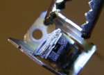
Like I promised. Here are some macros of my diode. I'll post different angles of the diode, so that it might help the curiousity of some to see this thing up close. This is the top view.
 

Attachments

  • IMGP0332.jpg
    IMGP0332.jpg
    62.9 KB · Views: 155
Joined
Jun 29, 2007
Messages
79
Points
0
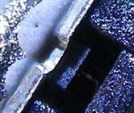
Here, a close up, of the last image, full pixels croped from the original image (i.e. it's not been resized, just cropped). This is what I'm pretty sure is just the diode material.
 

Attachments

  • IMGP0333_2.JPG
    IMGP0333_2.JPG
    48.3 KB · Views: 111
Joined
Jun 29, 2007
Messages
79
Points
0
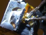
Last one, this is just the pins. This diode happened to just have two pins. I think it was the IR one that had the 4 pins, with two not being used.
 

Attachments

  • IMGP0334.jpg
    IMGP0334.jpg
    95.8 KB · Views: 153

Daedal

0
Joined
May 23, 2007
Messages
2,277
Points
0
Well... this is better than an "open can" diode! lol ;D

Yours actually has a cover on top, which also helps collimate the output I suppose. Nice pictures... this does look intriguing to me... :D

Thanx, and glad you got it working;
DDL
 

chimo

0
Joined
Jun 20, 2007
Messages
650
Points
0
This looks like an ideal candidate for a TEC (or a big heatsink)! The flat substrate the LD is mounted on would ensure a short thermal path to the TEC. In other words, you could pull the heat away very quickly with that device.

Ideally you would want to minimize the thermal barriers so removivg the didode from teh assembly would provide best results but it is more risky.
 

Gazoo

0
Joined
Jun 9, 2007
Messages
3,206
Points
38
It looks like a mini b mount or something. I don't know as I have never seen anything like it. Thanks for the pics.
 

Daedal

0
Joined
May 23, 2007
Messages
2,277
Points
0
chimo said:
This looks like an ideal candidate for a TEC (or a big heatsink)! The flat substrate the LD is mounted on would ensure a short thermal path to the TEC. In other words, you could pull the heat away very quickly with that device.

Ideally you would want to minimize the thermal barriers so removivg the didode from teh assembly would provide best results but it is more risky.


I would definitely try that! That seems so worth it to just slap it on a TEC and see how high it can get to. I'm sure pseudo will offer you a TEC for a great deal ;)

--DDL
 
Joined
Jun 29, 2007
Messages
79
Points
0
Forgive my ignorance, but is a TEC a Thermo-Electric Couple, like a Peltier cooling device?

In a related question... where do you guys get thermal epoxy from? My radio shack doesn't carry it anymore, and that was the only place I could think of that would have it.

And Daedal, you were right about my diode, it like 4 volts a lot better than 3. I've got it burning pretty good now with 4.8 volts going into the driver (which jumps between 4.42 and 4.43 volts going to the diode) and I'm thinking the mA on the diode is about 330 mA. My Multimeter is from Harbor Freight, so I've got a 200 mA setting, and a 10 A setting, so it's reading about .33 on the 10 A setting. Running the diode for about a minute and a half, playing with focusing it, I managed to get it burning and it wasn't even warm yet. If using a TEC will help, I'm kinda scared about how much this thing can put out! Well, I hope those stats I just gave mean something to somebody.

Daedal, thanks so much for the driver design. It's helping me learn about electronics like you wouldn't believe! To be honest, before I got into lasers, I couldn't remember which color was negative/ground (and I'd taken an electricity class too), but now I remember Ohm's Law like the back of my hand, and I know which wire is ground. I've even figured out what colors are roughly at which wavelenths! Lasers made me smart! ;D
 

chimo

0
Joined
Jun 20, 2007
Messages
650
Points
0
falchionsmight said:
Forgive my ignorance, but is a TEC a Thermo-Electric Couple, like a Peltier cooling device?

In a related question... where do you guys get thermal epoxy from? My radio shack doesn't carry it anymore, and that was the only place I could think of that would have it.

Yes. Thermoelectric cooler (Peltier device).

For the thermal epoxy, you can get it at the Sandwich Shoppe: http://theledguy.chainreactionweb.com/index.php.
Arctic Alumina is good, Arctic Silver is better

Paul
 

Gazoo

0
Joined
Jun 9, 2007
Messages
3,206
Points
38
falchionsmight,
It should make a very powerful burner. Just be careful not to get smoke or anything else in that diode. I do have a question. How did you know which leg on the diode is positive? The reason I am asking is because I might try to get one.
It appears as though the diode is epoxied to the heat sink assembly. You could try to separate it very carefully.

There has been some talk around about making our own TEC's using a peatier junction. The price of peltier's is cheap. The problem is condensation that will form, but it might not be a problem if we run short duty cycles. It is something I want to try.

The direct link to the thermal compound follows. I need to get some too.

http://theledguy.chainreactionweb.com/product_info.php?cPath=48_39&products_id=792
 
Joined
Jun 29, 2007
Messages
79
Points
0
I used the diode test on my Multimeter to find which leg to connect to. Then I soldered leads to them (helping hands are amazing, I bought them to use for all this close up soldering with the LDs, and now I don't know how I lived without them! Daedal, you should really get some!). Then I sharpied the postive leg red, now I know which one to connect to (I got the sharpie idea from Kenom).

Gazoo- Building our own TECs? That sounds AWESOME! I'd rather build something than buy it, so that sounds like a great idea to me. (Plus, I have this desire to build a TEC based portable AC unit that runs off batteries and solar power... because there's a cabin my family goes to at the lake, and it gets really hot in there, but there's no power, or AC, so the idea was to build my own... but Peltiers being used for this didn't seem to fit my needs very well, but if there was a way to make my own, I might be able to get it to work). Do you have a link Gazoo to this DIY TEC discussion? It sound awesome. Thanks for that info.
 

Gazoo

0
Joined
Jun 9, 2007
Messages
3,206
Points
38
There is no way I could get by without my helping hands. Peltier junctions are very inefficient. To give you an idea, I have run my ice cooler with a 7 amp battery, and it only ran for about an hour.

I do think it would be fun to experiment with one for cooling a diode. I have an old cpu heat sink with a fan mounted to it. It could be used to cool the side of the peltier that gets hot. I am going to try it with a low wattage peltier whenever I get around to doing it.

There is a lot of information on google regarding TEC's. Just search for it and a ton of stuff will come up. VaThink was experimenting with it and the link follows:

http://www.candlepowerforums.com/vb/showthread.php?t=166188
 

Daedal

0
Joined
May 23, 2007
Messages
2,277
Points
0
falchionsmight said:
Daedal, you were right about my diode, it like 4 volts a lot better than 3. I've got it burning pretty good now with 4.8 volts going into the driver (which jumps between 4.42 and 4.43 volts going to the diode) and I'm thinking the mA on the diode is about 330 mA. My Multimeter is from Harbor Freight, so I've got a 200 mA setting, and a 10 A setting, so it's reading about .33 on the 10 A setting. Running the diode for about a minute and a half, playing with focusing it, I managed to get it burning and it wasn't even warm yet. If using a TEC will help, I'm kinda scared about how much this thing can put out! Well, I hope those stats I just gave mean something to somebody.

I am very excited for you falchionsmight! This is awesome! You managed to get something that many, if not most, have not seen before. This would definitely be a very interesting project to carry with the help of TEC cooling as this little diode could possibly, given its shape and design, break 400mW of output power. If you were saying that at around ~180mA it was burning electrical tape then you are looking at around 100mW output! That is fantastic! You really seem to have a 'freak' diode, and that is a good thing... ;) :D

falchionsmight said:
Daedal, thanks so much for the driver design. It's helping me learn about electronics like you wouldn't believe! To be honest, before I got into lasers, I couldn't remember which color was negative/ground (and I'd taken an electricity class too), but now I remember Ohm's Law like the back of my hand, and I know which wire is ground. I've even figured out what colors are roughly at which wavelenths! Lasers made me smart! ;D

Falchionsmight, thank you very much and I am glad I could be of any help. This is honestly the beauty of this hobby. It's not only about the knowledge of the topic, but also about the application and what we get working. It's more of a group effort and a nice group activity than most other hobbies, especially ones where all you do is 'like pointing lasers' as my GF would say... ;)

I am trying to find the best design for a switching power supply so that I could power a peltier and be able to control it reasonably well. I know it gets COLD and HOT quickly, so having it continuously switching on and off is better than having it constantly on or off. It also helps with the heat dissipation on the heat sinked side of things. Another thing I am trying to implement in the circuit is a thermo-resistor. One of those that would be able to shut off the current supply at about 10 degrees Celsius would be amazing! It would make the circuit design very easy to duplicate by anyone, and safe to run on regular basis. The other thing is most of the time these resistors would 'slope' to a complete shut-off point, which is even better given the fact that the supply would be sloping as the temperature gets closer and closer to the desired temperature of the diode. If anyone has any suggestions, please let us know.

As regards to the thermal paste, I personally buy mine from eBay. If you search for Arctic Silver on eBay you will find tubes of this stuff for very cheap. The more you buy, the more you save on shipping. This stuff is good to have handy with all laser projects. Try to grab some thermal paste and 2-part thermal epoxy of the arctic silver stuff, and you will never regret any penny spent on it.

GL and keep us updated. I'm anxious to see what this beauty can put out! :D :D

--DDL
 
Joined
Jun 29, 2007
Messages
79
Points
0
Thanks Daedal, and Gazoo. Now you guys have me put on the spot, lol. If I kill this diode... it will be a very sad day, but considering I've got Daedal's driver, which so far had been very, very stable, I probably won't be killing anything for a little while. I'll probably get the driver off the protoboard later tonight... so that I'll have something that will be super solid, and then when I see how big the driver is, I can start thinking about housings for my wonderfully dangerous laser.

Just to run this by you guys, I'm curious what possibilites there might be in running a diode with a liquid cooled system. Then you could use the pellietier to cool the liquid before it reaches the diode, then we don't have the problem of water condensing on the pelitier, since it won't be getting the diode wet (the only thing I see is being sure the liquid doesn't freeze... maybe some anti-freeze would work well).


Top