Welcome to Laser Pointer Forums - discuss green laser pointers, blue laser pointers, and all types of lasers

LPF Donation via Stripe | LPF Donation - Other Methods

Links below open in new window

ArcticMyst Security by Avery

Homemade Scanning Laser Color Projector/TV

Joined
Dec 23, 2008
Messages
3,948
Points
63
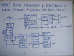
Blanking is basically turning the laser off so there isn't connecting lines. Go check out the laser shows section. There are some great tutorials and explanations.


zmr

0
Joined
Dec 16, 2010
Messages
3
Points
0
Thanks. But, suppose SLTVM uses negative sync., than there will be no connecting lines??? :yabbem::yabbem:
 
Joined
Oct 26, 2007
Messages
5,438
Points
83
Thanks. But, suppose SLTVM uses negative sync., than there will be no connecting lines??? :yabbem::yabbem:

You don't need "connecting lines" between pixels of a "raster" laser display because the pixels are already adjacent. Blanking is used to keep the laser off for intermediate positions that shouldn't be drawn. If he's using a "real" TV-based output, he'll blank it when one horizontal line is drawn and the X position needs to return back to the left side of the image, just like a CRT.
 

zmr

0
Joined
Dec 16, 2010
Messages
3
Points
0
That's exactly what I mean:

We don't need "connecting lines" between pixels of a raster.
But, we should keep the laser off during the back traces.
Now suppose that SLTVM uses negative sync.-TV based-video signal as an input to the laser driver, which consists of a single NPN transistor.
Then, laser will be automatically off during the back traces.

So, SLTVM blanks what?
 
Joined
Oct 26, 2007
Messages
5,438
Points
83
That's exactly what I mean:

We don't need "connecting lines" between pixels of a raster.
But, we should keep the laser off during the back traces.
Now suppose that SLTVM uses negative sync.-TV based-video signal as an input to the laser driver, which consists of a single NPN transistor.
Then, laser will be automatically off during the back traces.

So, SLTVM blanks what?

It probably just zeroes the output signal to the laser for the duration of the blanking, in the same manner that it is done in CRTs.
 
Joined
Apr 28, 2009
Messages
63
Points
8
Thanks for the discussion.
I accept that this point needs some explanation.
Since our fast mirror vibrates sinusoidally, laser traces a sinusoid.
That's why we should delete all odd(even) numbered lines and all odd(even) numbered fields.
This kind of blanking is somewhat different from the case in CRTs.
 
Joined
Dec 16, 2010
Messages
3
Points
0
sltvm2007: Can you show us some higher quality with better view of your fast mirror construction ?!

i am interested to use polygonal mirrors , do you have some suggestions !?

is there any solution for fast scanning ?!
 
Joined
Apr 28, 2009
Messages
63
Points
8
Reply to clurado:

OK. I will try to take a closer picture.

I think that polygonal mirrors are good only for slow axis.
This point have been discussed in this thread.

As far as I know, Kuntman's fast mirror is the simplest solution for fast scanning.
Maybe you mean something else by "solution"!?
 
Joined
Dec 16, 2010
Messages
3
Points
0
So how did you synchronize fast axis & slow axis with input composite signal ?! i think this is very important because non of galvanometer or the fast mirror are linear ? so how did you manage them ?!
 
Joined
Apr 28, 2009
Messages
63
Points
8
In this scanner we use a resonant fast mirror.
It is not linear, but it is finely tuned to the frequency of the input horizontal sync. pulses.

We also use a resonant galvo for vertical scanning, for simplicity.
If you like, you may use some nonresonant scanning method for slow axis.
At low frequencies synchronisation is not much a problem. It can be achieved by means of a feed-back control.

You will find below a closer view of the fast mirror of Kuntman's scanner.
 

Attachments

  • closer view.JPG
    closer view.JPG
    95.4 KB · Views: 972
Joined
Apr 28, 2009
Messages
63
Points
8
new! Block diagram: No blanking!
 

Attachments

  • Block Diagram for Kuntman's Laser  Scanner-Projector.JPG
    Block Diagram for Kuntman's Laser Scanner-Projector.JPG
    99.8 KB · Views: 1,526
Joined
Apr 28, 2009
Messages
63
Points
8
New! Biaxial Mirror for Kuntman's Scanner
 

Attachments

  • Biaxial Mirror.JPG
    Biaxial Mirror.JPG
    81 KB · Views: 913
Joined
Aug 13, 2011
Messages
80
Points
0
I love this!
Finally someone with guts and skills :)

Just wanted to chime in and ask if this might be worth CNC'ing some tiny parts for.
I've been playing with biaxial mirrors and have a setup that may work. It needs some parts cnc'd though and now that my cnc is actually working I can finally do it.

Basically the mirror is fixed on a fiberglass caddy that pivots in both axis with a magnet underneeth. A set of SMD inductors are driven to pan/tilt the mirror. The whole thing is about 8mm accross with a 3-4mm mirror surface and a total weight of less than a gram.
 
Joined
Apr 28, 2009
Messages
63
Points
8
I love this!
Finally someone with guts and skills :)

Just wanted to chime in and ask if this might be worth CNC'ing some tiny parts for.

Sorry, I dont understand what you are asking me.
Will you please express it in a simple wording.
I also dont know what "guts and skills" mean. Is it an idiom?
Thanks.
 
Joined
Aug 13, 2011
Messages
80
Points
0
I think this is a advanced project and I am happy that someone wants to try it.

I have been thinking of doing this myself and so far I have only been playing with the x/y mirror.
http://kreature.org/projects/xy_laser/xy_galvo_1.png
Doing this in two dimensions works on my small tests but the mirror needs to be scaled down for speed. CNC cutting the tiny parts may work.
 
Joined
Apr 28, 2009
Messages
63
Points
8
Yes, the mirror should be scaled precisely and laser CNC cutting is very important.
While I was working for the university I made use of this technique.
But it is not critical; simple filing is enough for many purposes.


Top