Welcome to Laser Pointer Forums - discuss green laser pointers, blue laser pointers, and all types of lasers

LPF Donation via Stripe | LPF Donation - Other Methods

Links below open in new window

ArcticMyst Security by Avery

DIY Homemade laser diode driver

Status
Not open for further replies.
Joined
Feb 23, 2008
Messages
2,832
Points
48
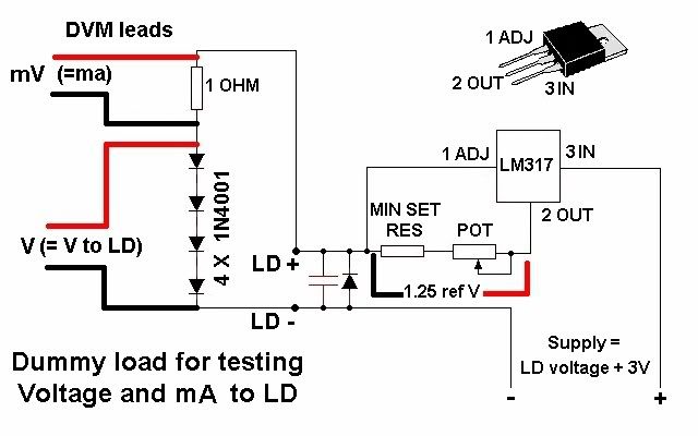
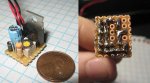
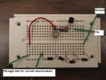
ok i just got finished making my driver but i guess i did something wrong b/c im not getting a mA reading at all on my dmm. i checked voltage coming in(5.99-6v from 2 cr123a batts) and voltage going out(between 5.35-5.37v) but no rating at all on mA setting. any1 have an idea where i may have went wrong? i used the parts from the post above and etched a pcb for them. i have already double checked the data sheets for the products to make sure all pinouts were correct.


chido

0
Joined
Dec 4, 2007
Messages
1,918
Points
0
Ok first, don't use normal CR123s, use rechargeable CR123s, or any other power source that outputs 7 - 9 volts.
And second, how are you testing your driver, you're supposed to test it like this:

clip_image001.jpg
 
Joined
Feb 23, 2008
Messages
2,832
Points
48
sadly i dont have a 1 ohm resistor til i get my order from mouser. would it be possible to use a 10ohm and still get an accurate reading?
 

chido

0
Joined
Dec 4, 2007
Messages
1,918
Points
0
Yeah, you can use any resistor you want, and then divide the mV by the resistor's resistance, so if it's a 10 ohm, you divide by 10, if it's a five, then you divide by 5, if it's a 845, then divide by 845. ;D
 
Joined
Mar 5, 2008
Messages
37
Points
0
Hello all, here is my first attempt at a driver circuit board. I should be receiving a laser diode soon to use in conjunction with it. Thanks for all of the schematics and tips.
 

Attachments

  • laser_driver3.JPG
    laser_driver3.JPG
    60.2 KB · Views: 6,636
Joined
Feb 23, 2008
Messages
2,832
Points
48
this is my first attempt with the smd parts listed above and a redrawn circuit to reduce size. since the biggest thing on the board is the capacitor i found a suitable replacement on mouser that had a smaller footprint so i could make it even smaller...the circuit should be no more than 11mm widthx15mm lengthx(at most 6mm height)

Mouser #: 74-293D476X0016C2TE3
Mfr. #: 293D476X0016C2TE3
Desc.: Solid Tantalum SMD Capacitors 47uF 16volts 20% $0.31


M

m.carroll

Guest
gn0stik said:
DDL, you say that you only used a 47uf because it's what was on the proto board you had. That's a very odd value cap for "just sitting" on the proto board. Radio shack doesn't even sell a 47uf 16v cap, individually, they do sometimes come in the packs though. They sell 47uf 32v, and 10uf 32v, but not specifically the one you said.

Also, I noticed you using a tantalum cap which are for use with ICs, does this matter?

If you had to pick one that rat shack sells, which one would it be? Better said, what would the ideal capacitor value be for this, application, seems everyone is using what you have used, but would  a different farad value be ok? A different voltage value?

Thanks.

I'd like to know this too, as I've purchased a 10uF 16V Tantalum from radio shack, for its size. Granted, I could go back and get another one of a different size, but I'd like to be able to use this one as its has the nicer lower voltage rating (I've read that the larger that, the longer the capacitor takes to reduce the spike), and it is a nice small package. If anyone can let both of us know that would be great!

@gn0stik - Tantalum Capacitors are just nonpolarized and usually smaller, there's virtually no difference in one of these or a electrolytic besides form-factor.
 

geek

0
Joined
Feb 13, 2008
Messages
62
Points
0
I just finished turning a 12 volt supply for an OLD standalone cd drive into a variable power supply to run my DDL driver. Anyway, when I set the power supply to 9V I see a max current through my 4 test diodes as ~220mA, when I turn the power supply down to 7.2V I see a max current of ~140mA. I am fairly certain my driver is correct, but this seems to imply that the resistor used to tune the LM317 is not the only factor that determines your output current. Any thoughts?
 

geek

0
Joined
Feb 13, 2008
Messages
62
Points
0
So if you test your circuit using the 4 diodes in series, and see the expected 3V drop along with a current that varies from 50mA to ~250mA or whatever you want your peak to be, then your circuit is working and you shouldn't fry any diodes correct? Regardless of how many volts you are running the driver with (as long as it is less than the 37V the LM317 accepts)? I really don't want to burn up any more diodes.
 

Gazoo

0
Joined
Jun 9, 2007
Messages
3,206
Points
38
geek said:
So if you test your circuit using the 4 diodes in series, and see the expected 3V drop along with a current that varies from 50mA to ~250mA or whatever you want your peak to be, then your circuit is working and you shouldn't fry any diodes correct? Regardless of how many volts you are running the driver with (as long as it is less than the 37V the LM317 accepts)? I really don't want to burn up any more diodes.

The LM317 is no mystery and very easy to work with. The following calculations always apply since it uses 1.25 volts for its reference voltage.

To calculate the resistor needed for a given current, take 1.25 and divide it by the current. So say you want to drive a SenKat diode with 250 ma's. 1.25 divided by .250 = a 5 ohm resistor.

Another way you could do this is to take 1.25 and divide it by the resistance. 1.25 divided by 5 = .250.

Next you will want to calculate the wattage of the resister needed. We know 1/2 watt resistors are common for use with the regulator. But to figure it out, simply take the 1.25 and multiply it times the current. 1.25 times .250 =.3125 watts.

The rule of thumb for the voltage going into the regulator is it should be 3 volts more than the voltage going to the diode. A SenKat diode running at 250ma's will have about 3 volts across it. Therefore a minimum if 6 volts is needed.
I recommend 6 nimh batteries or 2 RCR123's for use with Daedal's driver.
 

geek

0
Joined
Feb 13, 2008
Messages
62
Points
0
Gazoo said:
The LM317 is no mystery and very easy to work with. The following calculations always apply since it uses 1.25 volts for its reference voltage.

To calculate the resistor needed for a given current, take 1.25 and divide it by the current. So say you want to drive a SenKat diode with 250 ma's. 1.25 divided by .250 = a 5 ohm resistor.

Another way you could do this is to take 1.25 and divide it by the resistance. 1.25 divided by 5 = .250.

In my previous post I mention that adjusting the voltage input to the driver from 7.2 to 9 volts changes the max current output of my driver from ~140mA to ~220mA with the resistor and pot that I have on it. This seems to contradict your statement that only the 1.25 reference voltage and the resistance used effect the output current. The supply is a 12V 1.5A supply that I have attached an LM317 to in it's voltage regulation mode to so that I can vary the voltage. Am I seeing this effect because of my supply?

And you mention a minimum of 6 volts. Is there a maximum value? Or is it only limited by the abilities of the LM317?
 

Gazoo

0
Joined
Jun 9, 2007
Messages
3,206
Points
38
geek said:
[quote author=Gazoo link=1185701612/855#858 date=1204790829]

The LM317 is no mystery and very easy to work with. The following calculations always apply since it uses 1.25 volts for its reference voltage.

To calculate the resistor needed for a given current, take 1.25 and divide it by the current. So say you want to drive a SenKat diode with 250 ma's. 1.25 divided by .250 = a 5 ohm resistor.

Another way you could do this is to take 1.25 and divide it by the resistance. 1.25 divided by 5 = .250.

In my previous post I mention that adjusting the voltage input to the driver from 7.2 to 9 volts changes the max current output of my driver from ~140mA to ~220mA with the resistor and pot that I have on it. This seems to contradict your statement that only the 1.25 reference voltage and the resistance used effect the output current. The supply is a 12V 1.5A supply that I have attached an LM317 to in it's voltage regulation mode to so that I can vary the voltage. Am I seeing this effect because of my supply?

And you mention a minimum of 6 volts. Is there a maximum value? Or is it only limited by the abilities of the LM317?[/quote]

The maximum input to the 317 is 40 volts, but if you go above 9 volts a heatsink is recommended because the regulator will get so hot it's thermal protection will kick in.

If your current is changing with different voltages above 6 volts then you don't have something wired correctly.
 
M

m.carroll

Guest
m.carroll said:
[quote author=gn0stik link=1185701612/825#833 date=1204320906]DDL, you say that you only used a 47uf because it's what was on the proto board you had. That's a very odd value cap for "just sitting" on the proto board. Radio shack doesn't even sell a 47uf 16v cap, individually, they do sometimes come in the packs though. They sell 47uf 32v, and 10uf 32v, but not specifically the one you said.

Also, I noticed you using a tantalum cap which are for use with ICs, does this matter?

If you had to pick one that rat shack sells, which one would it be? Better said, what would the ideal capacitor value be for this, application, seems everyone is using what you have used, but would  a different farad value be ok? A different voltage value?

Thanks.

I'd like to know this too, as I've purchased a 10uF 16V Tantalum from radio shack, for its size. Granted, I could go back and get another one of a different size, but I'd like to be able to use this one as its has the nicer lower voltage rating (I've read that the larger that, the longer the capacitor takes to reduce the spike), and it is a nice small package. If anyone can let both of us know that would be great!

@gn0stik - Tantalum Capacitors are just nonpolarized and usually smaller, there's virtually no difference in one of these or a electrolytic besides form-factor.[/quote]

Nevermind, I was able to nab a relatively small 47uF 16V Electrolytic capacitor from my electrical engineering lab ;D
 
Joined
Feb 9, 2008
Messages
120
Points
0
i have a question.... why on the Pot are pins 1 and 2 connected? why not just pass the current through pin 1 and out pin 2?

LD_Driver_Schematic.JPG
 

chimo

0
Joined
Jun 20, 2007
Messages
650
Points
0
Ethator said:
i have a question.... why on the Pot are pins 1 and 2 connected? why not just pass the current through pin 1 and out pin 2?

LD_Driver_Schematic.JPG

The wiper is tied to a leg because the contact between the wiper and the resistive material is not always good.  Think it as the wiper bouncing off the surface and making intermittant contact.  Whe it does this, the resistance can go high (infinity) and the voltage can spike to try to maintain current.  If one leg of the wiper is tied to an end, the most resistance the circuit will see is the full value of the pot.
 

geek

0
Joined
Feb 13, 2008
Messages
62
Points
0
Gazoo said:
If your current is changing with different voltages above 6 volts then you don't have something wired correctly.

I now have two separate drivers, both doing the same thing. Both use a 47uF capacitor, an LN4001 diode, one 1/2 watt 5.1 ohm resistor, and a one turn 20 ohm pot. One uses the larger package LM317, one the smaller package. When I used 5 AAA's to supply the power I see a smaller current output than when I use 6 AAA's. The same effect is observed when I use a power supply and change from 7.2 to 9 volts. I measured the voltage between the Vout and Adj legs of the LM317 and it never reaches 1.25 volts. I realize the LM317 should keep the voltage across the adjust the same 1.25V and I should not be seeing this behavior. I'll get a picture up of the simplified (no diode or cap) version that exhibits the same behavior.
 

Attachments

  • DSC02846.jpg
    DSC02846.jpg
    40.6 KB · Views: 1,015
Status
Not open for further replies.


Top