Welcome to Laser Pointer Forums - discuss green laser pointers, blue laser pointers, and all types of lasers

LPF Donation via Stripe | LPF Donation - Other Methods

Links below open in new window

ArcticMyst Security by Avery

damaged Ophir 20C UAS-.5Y

equal

0
Joined
Oct 8, 2015
Messages
58
Points
8
hello,

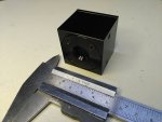
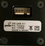
i have bought a used ophir 20C-UAS, but the sensor does not work.
Its a 6-pin Molex connected module. I have contacted Ophir and they tells me, this is a NDA Sensor .. i cant get any informations about the interface or Analog-Output.
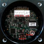
i think .. this Sensor is damaged, but the measureplate is ok ..

my idea:
trash the ophir board an build a new measure amplifier.
Has anyone done it yet? or should I develop myself?

greetings


equal

0
Joined
Oct 8, 2015
Messages
58
Points
8
ophir tells me .. the sensor with this serial number is a customer builded sensor (OEM). It is not a standard sensor. The RS232 protocol is unknown (no documentated ophir std protocol).
No Information, No datasheet, No support (only for the first customer, but not me)
With a own (std-) amplifier, i can read the value with a 16bit ADC an a µC (Atmel or Pic) to fake a ophir rs232 to use StarCom software.

but maybe you have a better idea ;-) I do not know about the output of the measuring plate ... first ask, then try ;-)

greetings
 
Last edited:
Joined
Jan 29, 2014
Messages
12,031
Points
113
Maybe this is too much trouble to work without a schematic, but a good electronics technician very well may be able to figure out what is wrong without one. I am a tech, so I'd try, perhaps if you don't work as an electronics technician it is far more difficult. Maybe someone here is familiar with them enough to give some advice, I just bought a similar unit so know what they are. Maybe Jerry can give some help, there are other members here who know these devices too.
 
Joined
Sep 20, 2008
Messages
17,622
Points
113
ophir tells me .. the sensor with this serial number is a customer builded sensor (OEM). It is not a standard sensor. The RS232 protocol is unknown (no documentated ophir std protocol).
No Information, No datasheet, No support (only for the first customer, but not me)
With a own (std-) amplifier, i can read the value with a 16bit ADC an a µC (Atmel or Pic) to fake a ophir rs232 to use StarCom software.

but maybe you have a better idea ;-) I do not know about the output of the measuring plate ... first ask, then try ;-)

greetings
First... how about a few pics on this specialized
OEM head... outsides and insides...
Can't really determine anything by just the words...
When you talk about the "measuring plate"..are
you referring to the Radial Thermopile Disk..:thinking:

Jerry
 
Last edited:

equal

0
Joined
Oct 8, 2015
Messages
58
Points
8
hi,

thanks for anwering ;-)
When you talk about the "measuring plate"..are
you referring to the Radial Thermopile Disk..
YESSS :-D
 

Attachments

  • Ophir_20C.jpg
    Ophir_20C.jpg
    321.9 KB · Views: 56
  • Ophir_20C_back.jpg
    Ophir_20C_back.jpg
    217.4 KB · Views: 59
  • Ophir-20C-UASV2.jpg
    Ophir-20C-UASV2.jpg
    321.6 KB · Views: 72
Joined
Jan 29, 2014
Messages
12,031
Points
113
Oh my lord, far more sophisticated than what I expected.
 
Joined
Sep 20, 2008
Messages
17,622
Points
113
hi,

thanks for anwering ;-)

YESSS :-D
I'm not in the shop right now...
I'll see what I can dig up tomorrow when
I'm back in the Shop..

The pics are really helpful...
From the pics I can see that there is a 4pin
molex connector with a 2pin Molex right beside
it.

I'm just guessing now... But the 4pin Molex
could be the same pinouts as used in the OPHIR
20C-A-1-Y heads. And the 2pin Molex could be
the RS232 Output pins....

You said that the head does not work... where
tod you apply power to test it a see if it had
an output ?? Use the pin IDs on your pic for
reference..

Jerry
 
Last edited:

BowtieGuy

0
LPF Site Supporter
Joined
Oct 14, 2012
Messages
6,090
Points
113
That sensors board looks a whole lot different than the Ophir 20C-A-1-Y, hopefully Jerry will be able to help out!


Ophir 20C-A-1-Y
1VqF5Tn.jpg
 
Last edited:
Joined
Sep 20, 2008
Messages
17,622
Points
113
That sensors board looks a whole lot different than the Ophir 20C-A-1-Y, hopefully Jerry will be able to help out!


Ophir 20C-A-1-Y
1VqF5Tn.jpg
Yeah it's different in that his Head has RS233
circuitry inside and perhaps keeps it's calibration
factor in memory.
But the 4pin Molex should/could have the same
Pinouts as the one you show..
At least that's my take on it so far...

Jerry
 

equal

0
Joined
Oct 8, 2015
Messages
58
Points
8
measurement and phone with ophir support helps me a little (unofficially :-D)

the only thing that is the same on all custom sensors with 6pin molex (95%)

1 - custom
2 - GND
3 - Vin (0.5 means that the sensor has clibrated 0.5V/1W - for 20W we need 10V + 2V => 12V, for 2W it is working with 6V)
4 -Analog Out
5 - custom
6 - custom

when i connect 12V power supply, the analog output works but the measurement confused me (~20mV random Steps)

0mW = -9mV, or -22mV
55mW = 0mV, or 18mV
103mW = 46mV or 68mV
2204mW = 1195mV or 1208mV or 1227mV or 1239mV

exact values between this steps are not possible. working with my selfmaded 10mm TEC LPM is more accurate :-D


the input laser are adjustet with my calibrated 20C-UAU USB-Head and StarCom. This is my reference head.

pin 1 has always ~5V output, when power is connectet, pin5 and 6 = 0V
 

equal

0
Joined
Oct 8, 2015
Messages
58
Points
8
Ophir 20C-A-1-Y
1VqF5Tn.jpg
[/QUOTE]

ouhhh ... this circuit is what i need :drool: :yh:

Greetings
 
Joined
Jul 4, 2008
Messages
2,499
Points
113
As we know this is a RS232 interface LPM sensor. The larger chip to the right looks to me like a TI conduit chip of some sort. You'll also notice that the sensor in the data sheet can be powered from +6V to +24V.

Also there is a pinout guide stating the following off the data sheet:

6 pin Molex connections: RS232 input, Ground, +Voltage, Analog signal out, high/low voltage or switch input when used, RS232 output


I'd be tempted to connect a USB to serial adapter to pin 1 and pin 6, (Rx=1 Tx=6)

Not too sure what else I can chime in here. I'd like to see that chip under the white sticker....
 
Last edited:
  • Like
Reactions: GSS
Joined
Sep 20, 2008
Messages
17,622
Points
113
measurement and phone with ophir support helps me a little (unofficially :-D)

the only thing that is the same on all custom sensors with 6pin molex (95%)

1 - custom
2 - GND
3 - Vin (0.5 means that the sensor has clibrated 0.5V/1W - for 20W we need 10V + 2V => 12V, for 2W it is working with 6V)
4 -Analog Out
5 - custom
6 - custom

when i connect 12V power supply, the analog output works but the measurement confused me (~20mV random Steps)

0mW = -9mV, or -22mV
55mW = 0mV, or 18mV
103mW = 46mV or 68mV
2204mW = 1195mV or 1208mV or 1227mV or 1239mV

exact values between this steps are not possible. working with my selfmaded 10mm TEC LPM is more accurate :-D


the input laser are adjustet with my calibrated 20C-UAU USB-Head and StarCom. This is my reference head.

pin 1 has always ~5V output, when power is connectet, pin5 and 6 = 0V


Yeah doing some reasearch in our files and on line..
my initial thoughts are not correct.
S_l is correct.. the Datasheet shows the pinouts..

http://www.ophiropt.com/laser--measurement/sites/default/files/20C-SH_20C-UAS_20C-UAU.pdf

The .5V/W refers to the Analog output.. it
means that for every 0.5 volts measured by
the head sensor it will represent 1 Watt of
Laser Power.

I would put 12VDC on pin #3 and Ground on
Pin #2. Then between ground and pin #$ I
would put a good quality DMM to read the
Analog voltage with a 1 Watt beam on the
Sensor..
If all is as expected you will get a reading
of 0.500 Volts on the DMM.
Using any other Laser power on the Sensor
Head just multiply the reading by 2 to get
the mW of that measurement.
Remember the data sheet states the head
does not measure correctly under 10mW.

Or.. try decoding the RS232 Signals on Pin#6.

If that does not give accurate results then
perhaps the Amp board has been damaged
and is defective.

Jerry
 
Last edited:
Joined
Mar 27, 2011
Messages
507
Points
63
Please do remember that supplying some semiconductor IC with reverse polarity could easily damage it.
There are chances that you already done that,

Anyway i do remember having schematic for 6 pin ophir.
I'll look for it.


Btw, let me know if you wish to throw it to rubbish bin..
I think i'll buy yours for parts :D
 
Joined
Jan 29, 2014
Messages
12,031
Points
113
My Ophir has a board much like the photo Jeff posted, equal's is quite sophisticated compared to mine. Surprised me how much more so.


Top