A couple week ago I deiced to start building a laser pulse circuit. I ended up having a 555 chip in a 'one-shot mode' shoot a trigger into a NPN transistor to power a 1 watt 808nM diode
The goal was to
A: have a diode deliver 40 J/cm^2 in a pulse
B: have the pulse be variable up-to .25 seconds (for safety)
C: Use a 555 chip and 1 watt 808nM diode
the values I used for the timing circuit
(using: tau=ln(3)RC )
Resistance: 2,312 ohms (for .25 second pulse), variable
Capacitance: 100 microfarads, static
pull-up resistor (for pin 2), 10,000 ohms (momentary switched to ground)
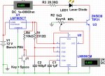
Since I was using a 7805 (rated at 1 amp), I thought that by using a 6.6 ohm in-series with the laser should provide a stable 2.2 volt, .454 Amp supply (5volt- 2.0 volts= 3.0 volts= .454Amps*6.6ohms). The laser was attached to the collector of a TIP31 transistor with pin3 going to base
looking up the data sheet for the TIP, the hfe for ~.500 Amps Collector was around 100, so the base current would have to be 4.54mA. Assuming a voltage of 5 on pin 3, I calculated the resistance to 1,100 ohms.
trying to the fire the diode resulted in nothing happening. Checking the values, I was reading 4 volts across the diode leads when triggered and 180mA.
Out of frustration I ended up smashing the project box.
What I don't understand is
1) if the hfe is ~100 at ~500mA (collector), why was it only supplying 180mA (collector)?
2)the purpose of the resistor was to drop the voltage down to 2.0 volts and provide 454 mA, yet why was the potential 4 volts across the diode?
Attached is the schematic
The goal was to
A: have a diode deliver 40 J/cm^2 in a pulse
B: have the pulse be variable up-to .25 seconds (for safety)
C: Use a 555 chip and 1 watt 808nM diode
the values I used for the timing circuit
(using: tau=ln(3)RC )
Resistance: 2,312 ohms (for .25 second pulse), variable
Capacitance: 100 microfarads, static
pull-up resistor (for pin 2), 10,000 ohms (momentary switched to ground)
Since I was using a 7805 (rated at 1 amp), I thought that by using a 6.6 ohm in-series with the laser should provide a stable 2.2 volt, .454 Amp supply (5volt- 2.0 volts= 3.0 volts= .454Amps*6.6ohms). The laser was attached to the collector of a TIP31 transistor with pin3 going to base
looking up the data sheet for the TIP, the hfe for ~.500 Amps Collector was around 100, so the base current would have to be 4.54mA. Assuming a voltage of 5 on pin 3, I calculated the resistance to 1,100 ohms.
trying to the fire the diode resulted in nothing happening. Checking the values, I was reading 4 volts across the diode leads when triggered and 180mA.
Out of frustration I ended up smashing the project box.
What I don't understand is
1) if the hfe is ~100 at ~500mA (collector), why was it only supplying 180mA (collector)?
2)the purpose of the resistor was to drop the voltage down to 2.0 volts and provide 454 mA, yet why was the potential 4 volts across the diode?
Attached is the schematic
Joe