Welcome to Laser Pointer Forums - discuss green laser pointers, blue laser pointers, and all types of lasers

LPF Donation via Stripe | LPF Donation - Other Methods

Links below open in new window

ArcticMyst Security by Avery

Blue laser 74W NUBM35 Portabl?

Borislav@87

Active member
Joined
Mar 20, 2022
Messages
355
Points
43
@RedCowboy
I made a diagram, but I don't know if it is. Of course there will also be two switches for each row of diodes. They will be before the LM338.

With this scheme, if I want, I can turn on only one row of diodes, which are 7. Because there will be two switches. I just want to know if the connection method is correct. Let me just say that I have no skills in this area and that's why I ask the same thing several times

I guess if I want the batteries to last longer I can put two power supplies of 9 batteries each. Each row of 7 diodes should have a separate power supply
 

Attachments

  • Screenshot_20221201_185842.jpg
    Screenshot_20221201_185842.jpg
    438.7 KB · Views: 15
Last edited:


Joined
Jul 10, 2015
Messages
9,931
Points
113
Looking at the back of the LM338 ( so you can see the pins ) you will notice they are off center, so with the pins on the top side of the center line the right pin is ( + ) battery in ( VIN )
The case ( body ) is the OUTPUT
The left hand pin is the ADJ.


NOTICE: I mislabeled this pic. Note when you connect your load to the " out " you have a voltage regulator, but for a current regulator you connect your load to the " ADJ "
In my pic below the physical connections are correct for a current reg. but the left pin I mislabeled...... the left pin is the " adj " pin and the case is the " output " but you connect your laser ( + ) to the ADJ. which is the left pin when using the 338 as a current reg.
So connect as shown but know I mixed up the labels for ADJ and V-out.
SANY6659.JPG

Pins-of-LM338-600x455.jpg
 
Last edited:

Borislav@87

Active member
Joined
Mar 20, 2022
Messages
355
Points
43
@RedCowboy
Many thanks for the wiring diagram. I just have to follow her and take note of what the VIN (+) is. Right, for the other row of 7 diodes I just have to do the same thing?
I plan to use a metal box for the body and put everything I need in it. The goal is to be easily portable. I'll probably have to come up with a lens adapter too so I can focus the beam up close
 
Last edited:
Joined
Jul 10, 2015
Messages
9,931
Points
113
The body of the LM338 is part of it's circuit, so if you heat sink both the LM338 to the metal body you need to use isolaters like these or the silicon type. It's a TO-3 package. Also you can mount the LM338 to a piece of aluminum heat sink and use a home made isolator to mount it in your device, plastic, wood, whatever.


Last edited:

Borislav@87

Active member
Joined
Mar 20, 2022
Messages
355
Points
43
Yes I understood 👍
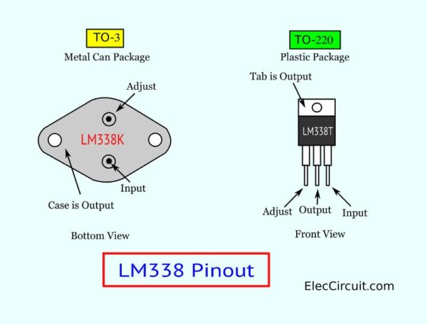
. Well, I'm going to mount them on aluminum plates, dabbing some thermal paste between the LM338 and the heatsink. I'll just insulate the heatsinks well if I'm going to mount them in a metal body.
 

Borislav@87

Active member
Joined
Mar 20, 2022
Messages
355
Points
43
@RedCowboy
He had mentioned lenses. I wonder which one to use so I can focus the beam. If there is one that can be used to achieve a maximally tight beam, that would be great.
 
Joined
Jul 10, 2015
Messages
9,931
Points
113
You can focus it down tight enough on the tabletop to cut through soup cans and razor blades, but you can't get it into a small beam over any real distance or get a super tight waist at any real distance because of the uneven divergence ( aggressive fast axis divergence ) of each chip and the alignment is ok, but it's not knife edged.

I had pretty good results with an expedient beam expander, but the right way is to make your own knife edged array from c-lens corrected beams, which will require effort and investment.

You can experiment with a concave then a convex lens of various focal lengths, your convex will need to be large enough to catch all the expanded output for it's focal length, also try some convex lenses for up close.

Best to start with whatever glass magnifying lens you have on hand, fix it in a jig so that it will be centered to the height of your array.

Use a fan to keep things cool as time flies when you're having fun.

Always practice laser safety.

sany6210-jpg.73645


sany6285-jpg.73707
 
Last edited:

Borislav@87

Active member
Joined
Mar 20, 2022
Messages
355
Points
43
@RedCowboy
Thanks.👍👍👍
Yes I will experiment with different lenses. So at long distances I will settle for the divergence from the factory lenses. For cutting close ups I will purchase a few lenses to test. I arrived with one that I have on hand and it worked. I used two cases side by side and it worked.
I see in the photos that the circuit breaker is at minus (-). I will do it the same way
 

Attachments

  • Screenshot_20221202_134358.jpg
    Screenshot_20221202_134358.jpg
    818.5 KB · Views: 6
Last edited:

Borislav@87

Active member
Joined
Mar 20, 2022
Messages
355
Points
43
@RedCowboy
I looked into the thread. There are many interesting projects. I placed an order for the 3W 1ohm resistors. I guess this is what I should have ordered (1ohm)
 

Attachments

  • Screenshot_20221202_224554_com.alibaba.aliexpresshd.jpg
    Screenshot_20221202_224554_com.alibaba.aliexpresshd.jpg
    135.1 KB · Views: 5
  • Screenshot_20221202_224550_com.alibaba.aliexpresshd.jpg
    Screenshot_20221202_224550_com.alibaba.aliexpresshd.jpg
    444.1 KB · Views: 5
Joined
Jul 10, 2015
Messages
9,931
Points
113
Yes you want ( 1 ohm ), they do list a 0.33 ohm but as they are 3W rated by using 3 x 1 ohm in parallel they share the waste heat so you can dissipate 9W

For instance 0.33 ohms will give you 3.5A and the resistors will waste 1.25V x 3.5A so 4.375W of waste heat, so 3 x 1 ohm in parallel is no problem, but a single 0.33 ohm will burn up.

Now if you add a 4th resistor in parallel you would have 0.25 ohms and get 5A that would mean 6.25W of waste heat, no problem if using these 3W rated resistors in parallel, but a single 0.25 would burn up.

You can get 5W and 10W rated resistors but they are physically larger, using 3W resistors in parallel is easier to work with and you can add a 4th resistor later to drive @ 5A

The rest of the waste heat is wasted by the regulator.
For instance if your laser diodes each draw 4.5V @ 3.5A then your 7 laser diode string will draw 31.5V @ 3.5A

Now there will be a little battery sag under load and the regulator needs a couple extra volts, plus batteries value drops as they discharge, so an 18650 fully charged stands at 4.2V so 8 cells will give you 33.6V but you really need 1 more cell to compensate for sag, discharge and to maintain the required 2V differential the regulator needs.

So 9 x 18650 call it 9 x 4V so 36V minus the 31.5V load ( your 7 laser diodes ) means 4.5V @ 3.5A of waste heat, so about 15-16 watts of waste heat, less as the cells discharge.

The resistors will waste 1.25V x 3.5A ( 4.4W ) so your regulator has to waste as much as 11.5W which is no problem as long as you use a heat sink, they are usually rated @ 15W but will take more in a good heat sink and even more with a fan, but this is why you want 9 x 18650 cells for your 7 laser diode string.

p.s. If you use cheap cells you may need to add a 10th cell when you switch on your 2nd LM338 and 2nd string of 7 laser diodes, depending on how much sag your batteries have under load. I used 17 x 18650 in series to power all 14 laser diodes with just 1 LM338, so it comes down to how much space you have for batteries because using a 2nd bank of 9 cells for the 2nd string will give you more runtime, but it takes more space for all the cells, so it's best to buy good quality cells, also using a regulator with a low dropout will extend runtime.
 
Last edited:

Borislav@87

Active member
Joined
Mar 20, 2022
Messages
355
Points
43
@RedCowboy
Thank you very much for the lecture 🙂 Written like this will help other people too 👍

I can't wait for the components to arrive and to hook everything up. I will share everything I do so that other enthusiasts can have information, and it is not small, because you shared a lot of details


I just wanted to clarify something. Right, with 9 pieces of 18650 batteries, I will power both rows with 7 pieces of diodes, as I have drawn it on my diagram. My thought is that 9 batteries will handle this consumption, because it will be multiplied by 2?

The two rows with 7 diodes each will consume 2x 31.5V

I don't know if you understand what I'm writing because I'm using a translator. In short, I am interested in whether I will be able to power all 14 diodes connected according to your scheme with 9 batteries
 
Last edited:
Joined
Jul 10, 2015
Messages
9,931
Points
113
As long as they are good quality IMR or INR formulated cells that don't sag a lot, but cheap cells that sag may not hold their voltage up very long or you may need to add an additional cell, this is where doing the math comes in and reading your regulators data sheet, but on average yes, for blasting cardboard boxes into flames in 10 second runs 9 cells will do just fine dozens of times before a recharge when powering both strings and running 1 string of 7 you can run for 60 seconds until your heat sink is warm a dozen times before needing a recharge or more, it depends on all the factors, your laser arrays heat sink is also a factor.

The 8 beam array I have running on 10 x 18650 cells will run until hot ( about 45-60 seconds depending on ambient temp ) then cool down and run again 10 times or more before I recharge, or I can run it for 15 seconds 50 times before a recharge, probably more but I often recharge before it needs it.
 

Borislav@87

Active member
Joined
Mar 20, 2022
Messages
355
Points
43
@RedCowboy

Turns out the dealer I work with doesn't have the NUBM35 available. There is a NUBM38 which I see is the same spec. I guess everything we have discussed so far applies to him as well

Thanks. I'll see how it goes and if the 9x18650s don't do well I'll add a second power supply with more 9x18650s for the other row of 7 diodes
 
Joined
Jul 10, 2015
Messages
9,931
Points
113
They both show the same spec sheet.
Yes driving a row of 7 diodes on 9 cells with an LM338 works very well, adding a 2nd pack of 9 cells for the 2nd regulator and 2nd row of 7 diodes will give you good runtime and if you want to add a 4th resistor to each to run at 5A then using the 2nd battery pack will give the best results.

( 1 ) 1 ohm resistor will give you 1.2 - 1.25A
( 2 ) 1 ohm resistors will give you 2.4 - 2.5A
( 3 ) 1 ohm resistors will give you 3.6 - 3.75A
( 4 ) 1 ohm resistors will give you 4.8 - 5.0A

Resistors are in parallel.
The drop across the Zenier diode inside the LM338 varies between 1.2 - 1.25, this is the reason for the variation, I tested my 3 x 1 ohm ( 0.33 ohm ) LM338 and it's putting out 3.6A to the nubm35
 
Last edited:


Top