Welcome to Laser Pointer Forums - discuss green laser pointers, blue laser pointers, and all types of lasers

LPF Donation via Stripe | LPF Donation - Other Methods

Links below open in new window

ArcticMyst Security by Avery

Bicron Surveyor M mod - PIC scaler BIG POST

Joined
Jul 4, 2008
Messages
2,499
Points
113
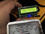
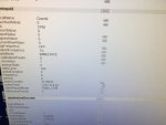
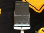
So a little update on the scaler project. I am in the final stages of assembling a counting program to simply display the output on a Mac. This program is using C++ assembly language to use the incoming data from the Yocto-PMW-Rx and modify its reporting behaviour.

Hz = CPS , edge count is divided by 2 to give raw Counts.

All this program is designed to to is display at the moment, no graphing or logging. Xcode has made this assembly process difficult as I can assemble it but cannot get the program to be freestanding nor display the incoming data.

The dependencies are listed on the top part of the C++ code.


If anyone has a background in C++ / programming would like to offer their recommendations I'm all ears. Eventually I'd like to be able to log and graph the output, maybe even be able to convert the CPS/ Counts to a metered dose. The raw counts could also be on a timer.

:thinking:


#include "yocto_api.h"
#include "yocto_pwminput.h"
#include <iostream>
#include <stdlib.h>

using namespace std;

static void usage(void)
{
cout << "usage: demo <serial_number> " << endl;
cout << " demo <logical_name>" << endl;
cout << " demo any (use any discovered device)" << endl;
u64 now = yGetTickCount();
while (yGetTickCount() - now < 3000) {
// wait 3 sec to show the message
}
exit(1);
}

int main(int argc, const char * argv[])
{
string errmsg;
string target;
YPwmInput *pwm;
YPwmInput *pwm1;
YPwmInput *pwm2;
YModule *m;

if (argc < 2) {
usage();
}
target = (string) argv[1];

YAPI::DisableExceptions();

// Setup the API to use local USB devices
if (YAPI::RegisterHub("usb", errmsg) != YAPI_SUCCESS) {
cerr << "RegisterHub error: " << errmsg << endl;
return 1;
}

if (target == "any") {
// retreive any pwm input available
pwm = YPwmInput::FirstPwmInput();
if (pwm == NULL) {
cerr << "No module connected (Check cable)" << endl;
exit(1);
}
} else {
// retreive the first pwm input from the device given on command line
pwm = YPwmInput::FindPwmInput(target + ".pwmInput1");
}

// we need to retreive both channels from the device.
if (pwm->isOnline()) {
m = pwm->get_module();
pwm1 = YPwmInput::FindPwmInput(m->get_serialNumber() + ".pwmInput1");
pwm2 = YPwmInput::FindPwmInput(m->get_serialNumber() + ".pwmInput2");
} else {
cerr << "No module connected (Check cable)" << endl;
exit(1);
}
while (pwm1->isOnline()) {
cout << "PWM1 : " << pwm1->get_frequency() << " CPS " << pwm1->get_dutyCycle()
<< " % " << pwm1->get_pulseCounter()/2 << "Counts " << endl;
cout << "PWM2 : " << pwm2->get_frequency() << " CPS " << pwm2->get_dutyCycle()
<< " % " << pwm2->get_pulseCounter()/2 << " Counts " << endl;

cout << " (press Ctrl-C to exit)" << endl;
YAPI::Sleep(1000, errmsg);
}
cout << "Module disconnected" << endl;
yFreeAPI();
return 0;
}


Joined
Jul 4, 2008
Messages
2,499
Points
113
A little update on this project, I have been very busy the last few months teaching at one of our local colleges here in Victoria and put the project on hold for awhile.

I am still working on the PIC ratemeter, but I decided to contact RH electronics out of Israel as Alexey B. has the exact ratemeter I am looking for which is based on a PIC18F. It is capable of counting up to 65.6 KCPS /3.6MCPM (which is overkill for a ratemeter even with the super fast pulses from organic scintillation detector mediums. )

Once I get the ratemeter working on my bicron surveyor M I will post a video showcasing the setup.

:thanks:
 
Last edited:
Joined
Jul 4, 2008
Messages
2,499
Points
113
Alright, well I have some success finally with the project. Pictures
uploaded:

So, I recently obtained a count rate meter from RH electronics. This device uses a newer pic18F variant and a pulse inverter to enable high-speed count rate acquisition from a combination of plastic scintillation probes - NaI/Tl probes. This rate meter is capable of counting 3.3v TTL logic pulses at 65.5KCPS. More than enough speed to see pulses from any survey meter.
The rate-meter also can send information in 2 ways via its built-in UART serial chip. It can report in short single number every second or it can report every minute with a CPM /CPS and average value over a variable serial baud rate. I've got mine on 9600 baud which is standard.
The rate meter also has a built-in battery charger which keeps the 2 cell micro-lipo cell charged.

RH electronics rate-meter can also power a high voltage from a built-in 5V output. I am using this count rate meter to extend my Bicron Surveyor M.
I am pulling CMOS logic pulses from the MC14538 (sig from pin 9) on the bicron's metering circuit. The pulses are fed into the signal input on the rate-meter.
Ground goes to the meter ground rail.

I turned on the meter and allowed the background to be measured for about 15 minutes using a simple pancake gm tube. (LND7311). The background was 32-45CPM.... averaging around ~38.6CPM over 4 minutes.
(0.0112mR/hr or 0.112uSv/hr)

I then tested the calibrated Ra226 source. Normally this source tests around 13800CPM. sure enough, over a few minutes sampling, I ended up with nearly the exact number after the conversion factor.

After this, I decided to try to measure a super hot ion chamber source.
A 180uCi (6.6MBq) Am241 oxide plated strip. The count rate on this is amazingly high as it is nearly a pure Alpha emitter. It also emits low energy gamma photons from the formation of Np237 @ 59.5KeV.

After 1 minute of sampling, the rate meter gave a reading of around 500KCPM, which is near the tubes saturation limits. On my 1.15" NaI/Tl scintillation detector nearly 800KCPM was measured.


1st Radium source.. look at the meter needle, and then look at the rate-meter display. (accuracy)
57488d1505110338-bicron-surveyor-m-mod-pic-scaler-big-post-img_2956.jpg


Now have a look at the Am241 source... I have saturated the GM tube here. ... on a NaI/Tl probe +600KPM are obtainable from this same source.

57489d1505110338-bicron-surveyor-m-mod-pic-scaler-big-post-img_2959.jpg


Here's my nice little toasty 180uCi of Am241 in a borosilicate glass vial.
The source is a AmO2 plated Gold foil strip.

attachment.php


"Calibrated" Ra226 source ~3.75mR/hr eq. Closer to 4mR/hr using an LND7311.
attachment.php
 

Attachments

  • IMG_2957.JPG
    IMG_2957.JPG
    120.8 KB · Views: 170
  • IMG_2956.JPG
    IMG_2956.JPG
    105.6 KB · Views: 155
  • IMG_2959.JPG
    IMG_2959.JPG
    102.4 KB · Views: 153
  • IMG_2960.JPG
    IMG_2960.JPG
    64.7 KB · Views: 168
Last edited:
Joined
Sep 20, 2013
Messages
17,462
Points
113
Cool. I've been following this since the beginning. Looks good. + rep
 
Last edited:
Joined
Jul 4, 2008
Messages
2,499
Points
113
Cool. I've been following this since the beginning. Looks good. + rep

Well, though it looks good I've run into a little issue... well, it's not little.

The MC14538B outputs an inverted 5V CMOS signal from pin 9...
the count rate meter requires a 3.3V TTL level signal to function properly.
This does 2 things to the rate meter, one it counts the off state of the output rather than the pulses, two, it causes an overload situation to the input buffer.

So, long and short... I need a CMOS to TTL converter as well as converting the voltage to 3.3v.

hmmm....... 4050 or 4049 might be in order.

Edit:

Going to invert the pulses with a MC4093 then use a logic level shifter to drop the signal to 3.3V. this should work better.
 
Last edited:
Joined
Jul 4, 2008
Messages
2,499
Points
113
Today I brought my CD4093B to my home and set up a simple inverter circuit.

attachment.php


The power supply is coming from an arduino uno (5V)
-the ECIO28P on the board is not being used(ignore it)

attachment.php


This is showing the survey meter displaying around 13,00CPM.
The rate-meter with the inverted input shows only 8600CPM at this point.


This is done by tieing 2 of the input pins together of any of the 4 Schmitt-trigger circuits. This locks the pins together so that when the signal in is low the output is in a 1 (on) state. When the signal goes to a 1 state the output is 0.

This is characteristic of NAND or (Negative AND) functionality.

However, this worked alright, but the voltage of the output was far lower than I wanted. This affected the count-rate of the rate-meter by RH Electronics. Many of the pulses were missed as they fell well below the input threshold of 3.3V.
At 5V input to the CD4093 the output was only about 0.9v.. Trying a supply upwards of 12V lead me to an almost acceptable ~2.7v ... still too low.


IC+4093.png


I suspect that there must be an easier way of dealing with this issue.
The original setup which was just directly connecting the survey meter to the signal input resulting in a far better result, though the input level was too high. Next, I will try a simple voltage divider and see what happens.
 

Attachments

  • IMG_2973.JPG
    IMG_2973.JPG
    217 KB · Views: 149
  • IMG_2974.JPG
    IMG_2974.JPG
    129 KB · Views: 147
Joined
Jul 4, 2008
Messages
2,499
Points
113
Major update on the Bicron Surveyor mod coming this weekend. Just got a custom piece of firmware from Yoctopuce team in Switzerland to solve a problem with the Yocto PMW-Rx data output. I will be integrating both boards on into this unit. Not only will I have the ability to output to Texas Instruments LABView software , I can also send the readings across a network for remote monitoring. I will also be able to datalog with the RH electronics rate-meter. 2 boards both working together.

Next thing will be to adjust the sensitivity of the Bicron board and and an LLD and window adj.

---->
 
Joined
Jul 4, 2008
Messages
2,499
Points
113
So, I have been given a beta firmware .byn file from the yoctoteam in Switzerland. This firmware makes it possible to display CPS/CPM on the Yocto-PMW-Rx.

This single board sensor interface broadcasts across a network and or if set up to do so, interface with TI's LABView software suite.

So, while my project is almost finished, I just wanted to show you that my bicron survey meter is now able to show in real time through livecharts.

The data is collected through the MC14538BCP (pin9) as an inverted signal.
The signal is 5.142V and is completely compatible with the Yocto PMW-Rx.

attachment.php


attachment.php


attachment.php
 

Attachments

  • IMG_2989.JPG
    IMG_2989.JPG
    117.5 KB · Views: 135
  • IMG_2987.JPG
    IMG_2987.JPG
    94.5 KB · Views: 134
  • IMG_2991.JPG
    IMG_2991.JPG
    123.5 KB · Views: 131
  • IMG_2995.mov
    13 MB · Views: 87
Last edited:
Joined
Jul 4, 2008
Messages
2,499
Points
113
Playing with some Radioisotopes from my Pb lined storage tin.

Today I had a go at debugging a new firmware for my Yocto-PMW-Rx board.

I loaded up the new .byn file and plugged it directly into my LG G3 phone running Yoctograph.

The .APIs loaded correctly and I was measuring CPM/CPS properly off the phone.

attachment.php


attachment.php


attachment.php


attachment.php
 

Attachments

  • IMG_3023.JPG
    IMG_3023.JPG
    132.1 KB · Views: 122
  • IMG_3028.JPG
    IMG_3028.JPG
    102.4 KB · Views: 124
  • IMG_3025.JPG
    IMG_3025.JPG
    136.6 KB · Views: 128
  • IMG_3022.JPG
    IMG_3022.JPG
    130.5 KB · Views: 123
Joined
Jul 4, 2008
Messages
2,499
Points
113
Some rather good news on the Bicron surveyor modification project.
I had a few days to have a look at the board and got hold of a USB oscilloscope and probed around the MC14538B chip.... I found a positive polarity pulse from Pin 10 of the IC... This means I have 2 separate outputs that can be used to pull data from.

The key is to use case ground when using either signal. I hooked both the yoctopuce PMW-Rx and the RH gamma rate-meter up and I instantly saw counts that were identical to each other. One data steam was displaying on Windows as a gauge and the other was showing on an LCD screen.

What I am going to do is to install a USB socket into the from of the meter, mount the board, then wire the Yocto PMW-Rx with a micro USB cable to the socket. This will allow me to update firmware as well as get usable data from the unit.
The positive pulses will be fed to the RH-Electronics Gamma ratemeter via an SMC connector.
 
Joined
Jul 4, 2008
Messages
2,499
Points
113
Just a few updates on my Bicron Surveyor MS project,

I have had to send my PMW-Rx back to the manufacturer due to what I believe might be a corrupted flash memory module or a glitch in the firmware. Yoctopuce in Geneva, Switzerland received the module I sent to them about 3weeks ago Wednesday and sent an upgraded version, v2.0 that is more accurate.

At any rate, I have a new module incoming and I will be integrating it into the meter as soon as I receive it.

Over the last several weeks I finally got around to installing my miniature CsI/Na scintillation detector into a housing utilizing a tiny Ukranian CsI/Na 16x25mm crystal and a Hamamatsu R1450 PMT.

the final result is a scintillation detector that runs optimally around (~1.5-1.6Kv)

I get between 300-400CPM for my background, and on my hottest check source (low energy gamma) Am241 (160uCi) approx 550,000CPM using my external count rate meter. ~ 550KCPM = 9.16Khz using the frequency measurement with the yocto-pmw-rx.

The first 2 pics are of the Ukranian crystal probe that uses a piece of old exercise equipment ( ferromagnetic with Ni added) and a 1" PVC plumbing end cap with a hole drilled into the top for adding a HV BNC connector.
The crystal and PMT and joined with optical grease then doubly heat-shrinked so as to moisture seal the two components. I then added 3x of thick black electrical tape and then inserted the unit into the pipe assembly.
and sealed both ends with HV silicone and epoxy.


The second 2 pics are of an RCA-4524 3" dia PMT that I found tucked into a drawer. I'd like to build a multi-purpose probe using a kit from iRad labs for gross counting/frisking.
 

Attachments

  • IMG_3086.JPG
    IMG_3086.JPG
    151.7 KB · Views: 15
  • IMG_3087.JPG
    IMG_3087.JPG
    164.3 KB · Views: 14
  • IMG_3085.JPG
    IMG_3085.JPG
    144.5 KB · Views: 14
  • IMG_3088.JPG
    IMG_3088.JPG
    127.2 KB · Views: 13
Last edited:
Joined
Sep 20, 2013
Messages
17,462
Points
113
I missed out on some of your posts while I was in the hospital for surgery. Getting caught up, I hope the PMT you are putting together is air tight and doesn't arc. Will be looking forward to your new posts on this project. Good luck. :yh: + rep.
 
Last edited:
Joined
Jul 4, 2008
Messages
2,499
Points
113
I missed out on some of your posts while I was in the hospital for surgery. Getting caught up, I hope the PMT you are putting together is air tight and doesn't arc. Will be looking forward to your new posts on this project. Good luck. :yh: + rep.

The PMT works like a charm and is insulated behind about 3cm worth of electrical epoxy on top of a few mils thick of 5Kv rated silicone wire.

I have had it running now for about a month and it works like a gem.

I am also able to use it for gamma spectroscopy and it gives " somewhat decent resolution" for its tiny size. about 7.6% PHR...
 
Last edited:
Joined
Sep 20, 2013
Messages
17,462
Points
113
I was looking at your spectrum in post #25. I found it impressive for the size of your setup. I'm glad your PMT works well and has been for awhile now. I will keep an eye on your progress as I find it all fascinating.
 
Joined
Jul 4, 2008
Messages
2,499
Points
113
I was looking at your spectrum in post #25. I found it impressive for the size of your setup. I'm glad your PMT works well and has been for a while now. I will keep an eye on your progress as I find it all fascinating.

50372d1456385703-putting-together-gamma-spectrometer-using-soft-mca-screen-shot-2016-02-24-11.32.57-pm.png


Yes, nice considering the size, but if you look at the spread here it's not nearly a fine as it could be! that large peak should be a skinny (59.54KeV) peak. CsI/Na is close to NaI/Tl in light output but it is denser. This changes the way that the Gammas interact with the Scintillation medium.

PHD (pulse height distribution) is not as good as NaI/Tl, though I am sure with a larger crystal I'd be getting better results? Maybe.. ? :thinking::thinking:
 
Last edited:
Joined
Sep 20, 2013
Messages
17,462
Points
113
Well, while you've been working on your gamma spectrum, I've gone another way and have been working on NIR, VIS and NUV with my spectrometers. Has worked out well as new wavelength diodes have become more available at very reasonable prices. Have measured many 473nm to 480nm and 501nm to 510nm. Am currently waiting on a "495nm" diode to measure. If it is over 490nm I will be getting one as they are ~$150.00 for one. If I could do a group buy, might be able to get them for ~$45.00 each for 22. ;)


Top