Welcome to Laser Pointer Forums - discuss green laser pointers, blue laser pointers, and all types of lasers

LPF Donation via Stripe | LPF Donation - Other Methods

Links below open in new window

ArcticMyst Security by Avery

AMC7135 blues. (Gazoo, need your assistance)

Benm

0
Joined
Aug 16, 2007
Messages
7,896
Points
113
I prefer a soldered-in 1 ohm shunt for most applications as long as i can permit the voltage drop one causes at that point. The 20A range is very useful for measuring total current though, especially in flashlight contstructions where you can use it to bypass the tailcap (switch).

About the ground thing: it would be nice to have a similar chip that goes in the positive end. For most builds is just very convenient to have the diode mounted to ground. When building green laser drivers the 7135 is good since those are mostly case-positive devices.


ron

0
Joined
Jan 31, 2008
Messages
43
Points
0
Ok....hang on for a sec:

1.) I am assuming this 'sense' resistor is the 5 ohm resistor that Paul put in his diagram. Now, I think the lower the resistance used, the more current will pass through it right? So I would need a 5 ohm resistor that is rated at 1 Watt or more right? I mean....since even inserting a 20 ohm resistor as I did before resulted in the resistor getting really hot really quickly, so a 5 ohm resistor will be worse. Even when I tried it with my pot. When it was at 100 ohms, it was ok. When I lowered it to about 5 ohms and powered the circuit, it began to glow, and started to smoke (Damn...am I glad that was not my LD in that situation :) ). Am I correct to say this?

2.) The casing should not touch ground? Do you mean the negative terminal of the AMC or the negative terminal of the battery? I do understand that the casing, since its connected to the negative terminal of the LD, it should not touch the batteries' ground, otherwise it will be bypassing the entire AMC circuit. But the negative from the AMC can touch the casing right?

Cool guys. Thanks. I got to get back to studying now. Hah... Cheers, and take care.
 

chimo

0
Joined
Jun 20, 2007
Messages
650
Points
0
ron said:
Ok....hang on for a sec:

1.) I am assuming this 'sense' resistor is the 5 ohm resistor that Paul put in his diagram. Now, I think the lower the resistance used, the more current will pass through it right? So I would need a 5 ohm resistor that is rated at 1 Watt or more right? I mean....since even inserting a 20 ohm resistor as I did before resulted in the resistor getting really hot really quickly, so a 5 ohm resistor will be worse. Even when I tried it with my pot. When it was at 100 ohms, it was ok. When I lowered it to about 5 ohms and powered the circuit, it began to glow, and started to smoke (Damn...am I glad that was not my LD in that situation :) ). Am I correct to say this?

The term "sense" is used when something is being used for feedback. It tells you something about what is happening in a part of the circuit.  Most feedback schemes require a feedback voltage.  To convert the current to a voltage, a resistance is put in the circuit and the voltage drop across that resistor is used for feedback.  Since this part of the circuit is "regulation overhead", it is desirable to keep the power losses low so a low sense voltage is desirable to reduce I^2*R losses.

ron said:
2.) The casing should not touch ground? Do you mean the negative terminal of the AMC or the negative terminal of the battery? I do understand that the casing, since its connected to the negative terminal of the LD, it should not touch the batteries' ground, otherwise it will be bypassing the entire AMC circuit. But the negative from the AMC can touch the casing right?

Cool guys. Thanks. I got to get back to studying now. Hah... Cheers, and take care.
   

That's correct, the LD ground should not be connected to battery ground.
 

ron

0
Joined
Jan 31, 2008
Messages
43
Points
0
I see. Then what explains my pot getting hotter as I reduced the resistance? I thought it made sense because the lower the resistance, the more current will pass through that resistor (instead of passing through the LD which was connected in parallel). So what I fear now is that my using a 5 ohm resistor, the moment i turn the power on, the resistor is going to get extremely hot & start smoking. But however, this phenomenon should not happen because if I use the I^2*R equation, the lower the resistance, the less the power loss. So why is it happening to me?

Has something else gone wrong?

Thanks Paul.
 
Joined
Oct 28, 2007
Messages
2,631
Points
48
well, I know this may have been said, but I dont have time to read.

the LED is not drawing the same current as an LD. try a dead LD as a load

GTG

bye
 

chimo

0
Joined
Jun 20, 2007
Messages
650
Points
0
Didn't you use a pot as your resistance? They are usually not rated for a very high power dissipation. I'm not surprised that it smoked.

Remember that you cannot ignore any elements in the circuit. If something is connected in parallel the current will settle on a ratio between the elements, if they are in series, the same current passes through each.

Consider the 100 ohm resistor. If the 7135 was to maintain a 350mA current through that, the voltage across it would have to be 35 volts. That would not happen with the 7135.

The 5 ohm resistor (alone in the cct) should dissipate around 0.6 Watts (0.35 * 0.35 * 5). It will get warm, but you only need it on long enough to measure the voltage across so you can calculate the actual current output of the 7135.

ron said:
I see. Then what explains my pot getting hotter as I reduced the resistance? I thought it made sense because the lower the resistance, the more current will pass through that resistor (instead of passing through the LD which was connected in parallel). So what I fear now is that my using a 5 ohm resistor, the moment i turn the power on, the resistor is going to get extremely hot & start smoking. But however, this phenomenon should not happen because if I use the I^2*R equation, the lower the resistance, the less the power loss. So why is it happening to me?

  Has something else gone wrong?

    Thanks Paul.
 

ron

0
Joined
Jan 31, 2008
Messages
43
Points
0
ok...I gave it a shot. And I ran into the same problems again:
I tried using a 5 ohm, 2 Watt resistor for the first circuit that you showed. When I measured the voltage across the resistor, the reading on my analog multimeter was 3 V. Now that means that the current from the AMC 7135 is 600mA. Also to note: the 5 ohm resistor got really hot, really quickly.

Isnt the AMC 7135 suppose to be a 350mA current regulator? What the hell is wrong with my circuit? Sigh....

Hope you will be able to help me.
 

ron

0
Joined
Jan 31, 2008
Messages
43
Points
0
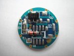
Here is how my AMC 7135 looks like. I dont think I am wiring it up the wrong way, but just to confirm. Can anyone show me where I'm suppose to connect what?
 

Attachments

  • P1010133.JPG
    P1010133.JPG
    44.5 KB · Views: 1,414

ron

0
Joined
Jan 31, 2008
Messages
43
Points
0
Guys...I'm sorry, but I dont have photoshop...so I cant shrink this photo. Sorry.
 

chimo

0
Joined
Jun 20, 2007
Messages
650
Points
0
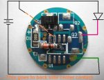
Here you go.
 

Attachments

  • AMC7135_DX_marked_up.jpg
    AMC7135_DX_marked_up.jpg
    30.1 KB · Views: 702

ron

0
Joined
Jan 31, 2008
Messages
43
Points
0
Hey Paul.

OMG!!! Are you absolutely sure about the wiring that you drew out on my AMC pic? Cause if you are, I have just found the source of my problems. I HAVE BEEN WIRING IT UP THE WRONG WAY!!!!!!!!!

You see the 2 little holes to the right of the '000' resistor, I wired the positive to that part.
The ground from the LD went into the part which you labeled as the ground going to the batteries.
And for me, the ground that was going to the batteries was on the other side of the AMC board - the outer ring.

Are you really sure about this wiring Paul? Sorry to sound like I'm doubting you.... but If you are sure....then I guess that I have got it all wrong to begin with....

Hope to hear from ya man. Thanks loads.
 

ron

0
Joined
Jan 31, 2008
Messages
43
Points
0
Preliminary testing: I modified my old AMC circuit to match yours, and i placed a 5 ohm resistor to measure the voltage across the resistor. Unfortunately, not seeing any voltage change (i.e. my multimeter reads the voltage as zero as if to say that there is no current passing through).

   I will try on a brand new AMC board. But first I need your reply first to see if you are sure of the connection diagram you gave me earlier. I have seen on the DX website previously, and here is the image that someone put up over there. They seem to connect the negative from the LD to the part labeled Q2. Shouldn't I do the same? Or is this one different?

Cheers man. :)
 

Attachments

  • AMC7135_Connection.jpg
    AMC7135_Connection.jpg
    88.9 KB · Views: 7,010

chimo

0
Joined
Jun 20, 2007
Messages
650
Points
0
ron said:
Hey Paul.

  OMG!!! Are you absolutely sure about the wiring that you drew out on my AMC pic? Cause if you are, I have just found the source of my problems. I HAVE BEEN WIRING IT UP THE WRONG WAY!!!!!!!!!

You see the 2 little holes to the right of the '000' resistor, I wired the positive to that part.
The ground from the LD went into the part which you labeled as the ground going to the batteries.
And for me, the ground that was going to the batteries was on the other side of the AMC board - the outer ring.

Are you really sure about this wiring Paul? Sorry to sound like I'm doubting you.... but If you are sure....then I guess that I have got it all wrong to begin with....

Hope to hear from ya man. Thanks loads.

What I have marked is good.

Note the text that indicates the orange dotted line goes to the other side of the board. The 2 little holes you mentioned are electrically the same as the center spot on the back (the holes are "vias" that connect one side of the board to the other).

The same concept applies for the grounding ring (note all the vias).

Good luck,

Paul
 

ron

0
Joined
Jan 31, 2008
Messages
43
Points
0
Hey Paul,

I tried your wiring with a new AMC7135, but it does not seem to work. I wired it up exactly the way you said to, but I used a 5 ohm resistor so that I can calculate the current. But when I tried to measure the voltage across the resistor, nothing.

Back to the drawing board . :( HeLp!!
 
Joined
Oct 28, 2007
Messages
2,631
Points
48
ron said:
Hey Paul,

I tried your wiring with a new AMC7135, but it does not seem to work. I wired it up exactly the way you said to, but I used a 5 ohm resistor so that I can calculate the current. But when I tried to measure the voltage across the resistor, nothing.

Back to the drawing board . :( HeLp!!
follow the diagram on DX. that is CORRECT!!

Jayrob had also told me to wire like the one on DX.


Top