ScottW
0
- Joined
- Feb 18, 2014
- Messages
- 93
- Points
- 18
9mm 445nm, Polished Black Zaser Build
Hello All,
I am new here, but have been making heavy use of the search feature and soaking up a lot of information. I decided it was only fair to try and contribute some content back to the forum!
This is only my second build, and my first build thread, so there likely won't be anything really new or unique presented. Yet I know from my own experience searching the forum that there can never be enough build threads, and that every photo adds a slightly new angle that may be just the angle someone needs -- so I hope some of this will be helpful and interesting to those building or contemplating a build of their own.
My photo skills need some work, and I haven't done a build thread before, so this won't be Pulitzer material but hopefully I will improve with practice and future builds.")
DIODE, MODULE, and DRIVER
I sourced the 9mm 445nm diode, module, and X-drive from Jordan (DTR). I don’t have a diode press nor am I confident enough to set driver current yet, so Jordan was a great help here.
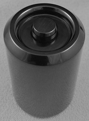
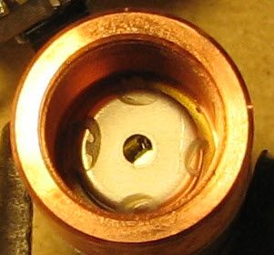
The diode, already pressed into it’s cozy copper and aluminum home (as received from DTR):
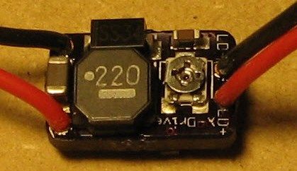
The elegant and adjustable Lazeerer X-Drive, leads attached and current preset to 2.1A. I am undoubtedly being over-cautious with 2.1A, but I was willing to give up a bit of power for better diode longevity.
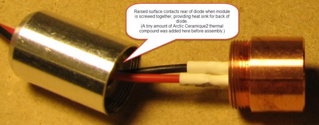
Since DTR was setting the driver current, I also asked him to solder leads to the driver and diode. I opted for leads between the diode and driver, rather than soldering the driver directly to the diode, for two reasons: First, I wanted to heat-sink the driver to the host pill. Second, I wanted the rear half of the module to make direct contact with the back of the diode for better heat dissipation. The new-style rear module half supplied (shown below) has a mating surface that directly contacts the back of the diode, as shown below. I added some Arctic Ceramique2 compound to that surface before screwing the module together.
LENS
I decided to use the stock lens that comes with the 9mm diode, both because it provides great output power and, well, let’s face it: The price can’t be beat since it comes with the diode.
The lens arrived still mounted (glued) in its original holder. I read a lot of methods involving a bath in acetone or alcohol, but in the end decided against any chemicals and just went straight to mechanical means.
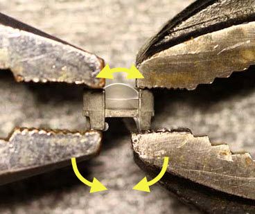
The original for the below photo is quoted from a post by Blord and is a great closeup showing how to grip the lens holder with pliers for the removal. I actually used vice-grips for more controlled grip ("use’em if you got’em"), and I have added some yellow arrows to Blord’s original photo to depict the “rotating” force I used to gently spread the two wings of the holder apart.
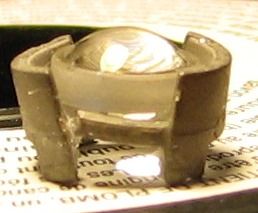
The holder material is very brittle – be gentle, and do this over a padded surface (like a towel) in case the lens falls out! The photo below shows the assembly after bending the two vertical wings outward. Note the fracture in the holder assembly, at the lower left of the lens, and the slight outward angle of the two vertical wings -- it didn't bend far before it snapped! The lens is free of the holder in this photo.
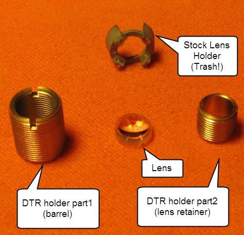
The lens had a very small amount of glue on the edges, which I carefully removed with a razor blade. The final step was cleaning my grubby fingerprints off the lens with a microfiber cloth, and installing it into the holder purchased from DTR:
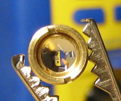
Lens installed in DTR's Lens Holder:
THE HOST
There are a lot of talented machinists here, providing a lot of great hosts from which to choose. I eventually picked the Zaser, manufactured by Mike Crouse (mrcrouse) and his Dad. My reasons included (1) It is a 2x18650 host (I have lots of quality 18650’s and a good charger for them); (2) It has a good amount of finned aluminum mass for the heat sink; (3) It is manufactured/shipped domestically, and (4) It looks great! Having previously purchased a C11 kit from Mike and reading comments from other satisfied Zaser customers, I was certain it would be a good choice.
Once I placed the order, my Zaser was custom manufactured, anodized, polished, and handed over to USPS in less than a week. USPS then took 4 days to work their special combination of transportation, attempted destruction and eventual delivery, after which it was in my hands.
ASSEMBLY SNAG
I had intended to affix the driver to the pill or the back of the finned head, but ran into a minor problem: The Zaser doesn’t have a solid pill; rather the pill is essentially a threaded ring with a contact board soldered into it. And there is not much room between the pill and the back of the heat sink. So where to put the driver board? There is plenty of room for the mini X-drive board in the 12mm bore, behind the diode module, but I had wanted to heat sink the driver to the host.
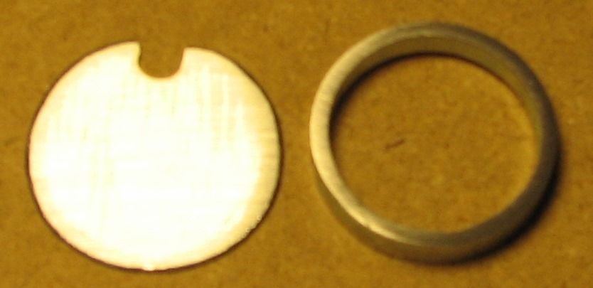
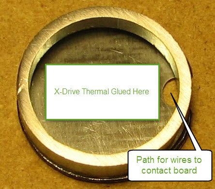
My solution was extend the pill by fabricating two additional parts. First, I cut a round piece of sheet aluminum, the same diameter as the pill, with a hole at one edge for wires between the contact board and driver. This piece became the solid top for the pill. Second, I cut a 3/16” long piece of tubing whose outside diameter was nearly the same as the inside diameter of the Zaser. I placed this between the pill and the back of the Zaser’s finned head, forming a spacer to prevent the pill from screwing in all the way, thus leaving room for the driver board. Here are the two parts, first by themselves and then stacked just as they will be stacked on the pill, with a diagram showing where the X-drive will be affixed:
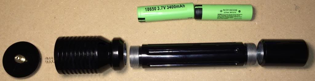
The only disadvantage to this approach was losing a 3/16” of battery compartment length. There is still plenty of room for unprotected cells (my Panasonic 18650Bs fit with room to spare), but most protected cells would prevent the tail cap from screwing on fully. That’s not a problem for me – I prefer the Panasonic 3400mAh unprotected cells.
FINISHING THE BUSINESS END
After thermal gluing the X-drive to the new pill cover, I soldered the leads to the contact board. I then pushed the module all the way through the bore from the rear, so the wires could twist freely as I inserted my spacer ring, the X-drive (affixed to my pill extension), and finally the pill with contact board. I screwed in the pill until it bottomed out on the spacer ring, then (working from the front side) put some Ceramique2 on the module, inserted it and tightened the set screw. (Arggghhh! I had several photos of this step, then somehow lost them when uploading to photobucket. If it weren't for the messy Ceramique2, I would just take it apart again... Oh well, aside from the extended pill shown above, all are pretty standard and have been seen in other builds.)
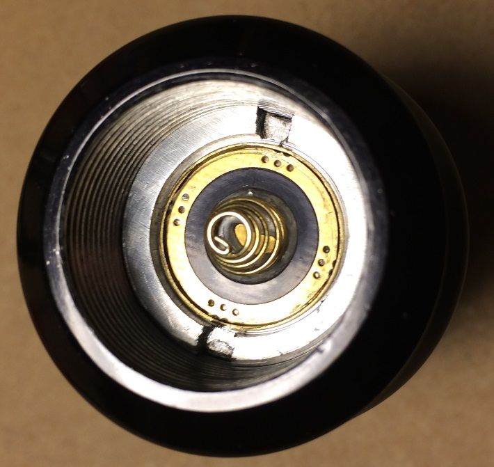
Here’s the back side of the finished head, with the pill/contact board installed:
PUTTING IT ALL TOGETHER
I installed the lens into the Zaser’s focus ring, and laid out all the parts for final assembly. One last check with the ohmmeter to make sure the tailcap switch was in the OFF position, then it was time to put it all together.
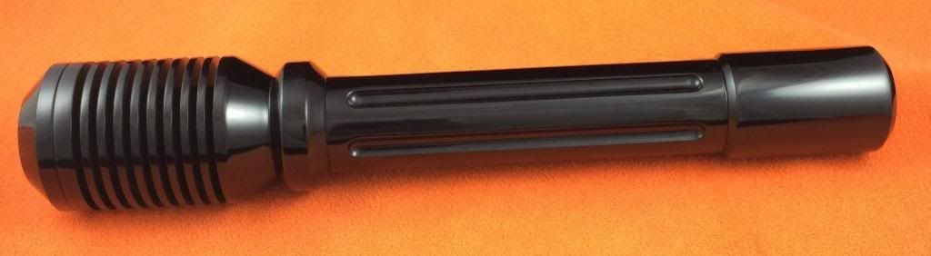
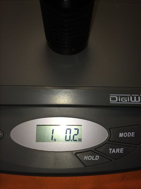
COMPLETE PACKAGE
Just over 1 pound with batteries.
MOMENT OF TRUTH
Goggles on, Check. Pointed at a light surface 45 feet away, check. No pets, children, or pesky spouses around. Check, check, and check.
Pushed the button and… The room was bathed 445nm blue! I regret to say that my photo skills come anywhere close to doing it justice...
MY KINGDOM FOR AN LPM
I don’t have an LPM, as I am still trying to decide between the reasonably priced Radiant X4 versus a budget-busting Ophir based system. So I can only GUESS at the actual output power. The driver is set at 2.1A and I'm using the stock lens, so based on others' results I am guessing output is about 2.6W. If I get access to an LPM soon, I will update this review with a measurement.
*** UPDATE 17-Apr-2014 *** My Radiant X4 arrived! The guess at 2.6W above wasn't too far off; according to the radiant I'm hitting a bit over 2.8W. Really happy to see that, especially with only 2.1A input.
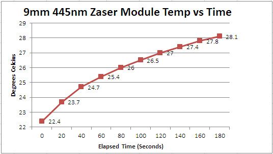
TEMPERATURE TEST
I was curious how well the heat generated by the diode was dissipated by the aluminum head of the Zaser. I have a reasonably accurate (+/- 1C) infrared thermometer, and was able to use it to measure the temperature of the copper diode module during operation (lens out, measuring inside the module threads). This obviously doesn't get actual diode can temperature, but it is as close as I can get with the equipment I have, but keep in mind it is the MODULE temperature, a few mm in front of the diode, NOT the diode itself. Three tests were performed with 30 minute rests in between, and results were averaged to build the chart.
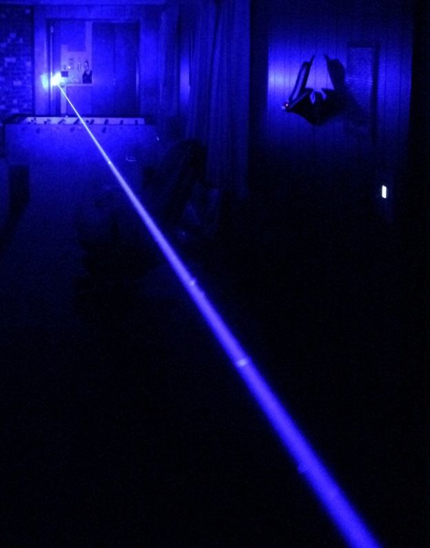
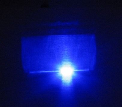
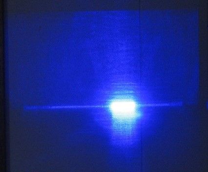
BEAM SHAPE
Beam shape is what I understand to be typical for the 9mm 445nm and stock lens. The size and intensity of the square area surrounding the main beam is surprisingly bright. Here is the best beam terminus shots I could get with my combination of camera and photo skills. The "spot" is actually smaller than it appears in the photo, as the brightness overwhelms the imaging sensor, but otherwise these are pretty good representations.
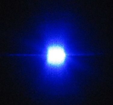
Substituting a 405/445nm AR coated 3-element glass lens cleans up the shape a lot, eliminating the square "splash" around the beam and making it more square than rectangular (presumably by clipping). (Note: This is the ONLY photo taken with the 3-element lens; all others were with the stock 9mm lens).
BEAM SHAPE WITH 3-ELEMENT LENS (All other photos, above and below this oint, use the stock 9mm stock lens)
CLOSING COMMENTS
The only challenge I had in this build was finding a place to glue the driver to the pill or host; and in retrospect, that probably wasn't necessary. While nice to have the driver heat-sinked to run continuously, it really doesn't need to run any longer than the intended duty cycle of the diode. So a good alternative would have been to just glue some thermal mass (like a piece of copper wire) to the driver chip, and place the driver in the 12mm bore directly behind the module.
Total cost was a bit more than $255. The diode, module, driver (including leads and current preset), lens, and lens holder was $125, while the Zaser with anodizing was $130. Add another $1-$2 for supplies (like arctic alumnia adhesive & arctic ceramique2 grease).
A HUGE thank-you goes to Jordan (DTR), not only for making quality components available, but for doing all the preliminary work (pressing the diode, soldering the leads, setting driver current, etc.) that makes a build like this so easy. Thanks to Lazeerer for the great X-Drive, to Mike (mrcrouse) for the well made and great looking Zaser host, and to FlaminPyro for the Flux that made contact board connections a whole lot easier. All very talented and helpful guys!
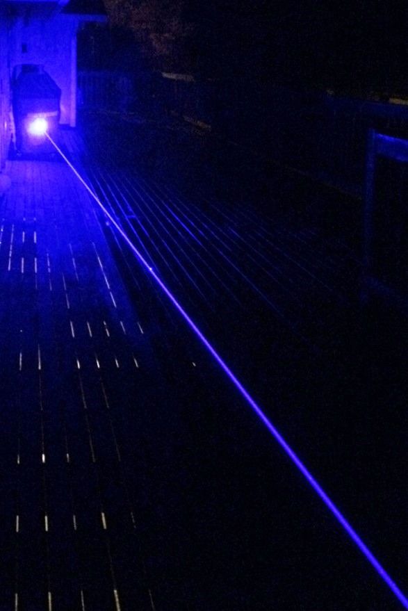
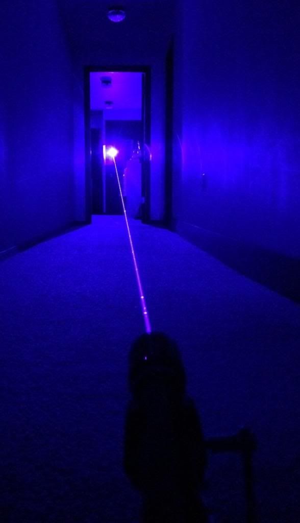
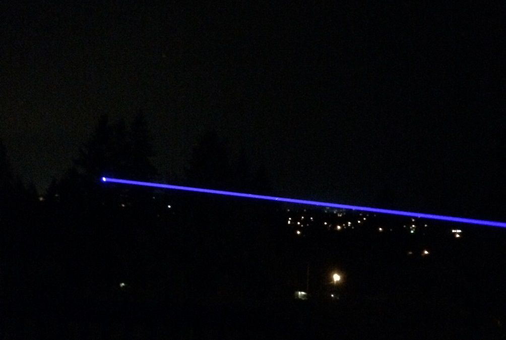
So that's it... I will now play my way off stage with a few more beam shots. :beer:
Hello All,
I am new here, but have been making heavy use of the search feature and soaking up a lot of information. I decided it was only fair to try and contribute some content back to the forum!
This is only my second build, and my first build thread, so there likely won't be anything really new or unique presented. Yet I know from my own experience searching the forum that there can never be enough build threads, and that every photo adds a slightly new angle that may be just the angle someone needs -- so I hope some of this will be helpful and interesting to those building or contemplating a build of their own.
My photo skills need some work, and I haven't done a build thread before, so this won't be Pulitzer material but hopefully I will improve with practice and future builds.
DIODE, MODULE, and DRIVER
I sourced the 9mm 445nm diode, module, and X-drive from Jordan (DTR). I don’t have a diode press nor am I confident enough to set driver current yet, so Jordan was a great help here.
The diode, already pressed into it’s cozy copper and aluminum home (as received from DTR):
The elegant and adjustable Lazeerer X-Drive, leads attached and current preset to 2.1A. I am undoubtedly being over-cautious with 2.1A, but I was willing to give up a bit of power for better diode longevity.
Since DTR was setting the driver current, I also asked him to solder leads to the driver and diode. I opted for leads between the diode and driver, rather than soldering the driver directly to the diode, for two reasons: First, I wanted to heat-sink the driver to the host pill. Second, I wanted the rear half of the module to make direct contact with the back of the diode for better heat dissipation. The new-style rear module half supplied (shown below) has a mating surface that directly contacts the back of the diode, as shown below. I added some Arctic Ceramique2 compound to that surface before screwing the module together.
LENS
I decided to use the stock lens that comes with the 9mm diode, both because it provides great output power and, well, let’s face it: The price can’t be beat since it comes with the diode.
The lens arrived still mounted (glued) in its original holder. I read a lot of methods involving a bath in acetone or alcohol, but in the end decided against any chemicals and just went straight to mechanical means.
The original for the below photo is quoted from a post by Blord and is a great closeup showing how to grip the lens holder with pliers for the removal. I actually used vice-grips for more controlled grip ("use’em if you got’em"), and I have added some yellow arrows to Blord’s original photo to depict the “rotating” force I used to gently spread the two wings of the holder apart.
The holder material is very brittle – be gentle, and do this over a padded surface (like a towel) in case the lens falls out! The photo below shows the assembly after bending the two vertical wings outward. Note the fracture in the holder assembly, at the lower left of the lens, and the slight outward angle of the two vertical wings -- it didn't bend far before it snapped! The lens is free of the holder in this photo.
The lens had a very small amount of glue on the edges, which I carefully removed with a razor blade. The final step was cleaning my grubby fingerprints off the lens with a microfiber cloth, and installing it into the holder purchased from DTR:
Lens installed in DTR's Lens Holder:
THE HOST
There are a lot of talented machinists here, providing a lot of great hosts from which to choose. I eventually picked the Zaser, manufactured by Mike Crouse (mrcrouse) and his Dad. My reasons included (1) It is a 2x18650 host (I have lots of quality 18650’s and a good charger for them); (2) It has a good amount of finned aluminum mass for the heat sink; (3) It is manufactured/shipped domestically, and (4) It looks great! Having previously purchased a C11 kit from Mike and reading comments from other satisfied Zaser customers, I was certain it would be a good choice.
Once I placed the order, my Zaser was custom manufactured, anodized, polished, and handed over to USPS in less than a week. USPS then took 4 days to work their special combination of transportation, attempted destruction and eventual delivery, after which it was in my hands.
ASSEMBLY SNAG
I had intended to affix the driver to the pill or the back of the finned head, but ran into a minor problem: The Zaser doesn’t have a solid pill; rather the pill is essentially a threaded ring with a contact board soldered into it. And there is not much room between the pill and the back of the heat sink. So where to put the driver board? There is plenty of room for the mini X-drive board in the 12mm bore, behind the diode module, but I had wanted to heat sink the driver to the host.
My solution was extend the pill by fabricating two additional parts. First, I cut a round piece of sheet aluminum, the same diameter as the pill, with a hole at one edge for wires between the contact board and driver. This piece became the solid top for the pill. Second, I cut a 3/16” long piece of tubing whose outside diameter was nearly the same as the inside diameter of the Zaser. I placed this between the pill and the back of the Zaser’s finned head, forming a spacer to prevent the pill from screwing in all the way, thus leaving room for the driver board. Here are the two parts, first by themselves and then stacked just as they will be stacked on the pill, with a diagram showing where the X-drive will be affixed:
The only disadvantage to this approach was losing a 3/16” of battery compartment length. There is still plenty of room for unprotected cells (my Panasonic 18650Bs fit with room to spare), but most protected cells would prevent the tail cap from screwing on fully. That’s not a problem for me – I prefer the Panasonic 3400mAh unprotected cells.
FINISHING THE BUSINESS END
After thermal gluing the X-drive to the new pill cover, I soldered the leads to the contact board. I then pushed the module all the way through the bore from the rear, so the wires could twist freely as I inserted my spacer ring, the X-drive (affixed to my pill extension), and finally the pill with contact board. I screwed in the pill until it bottomed out on the spacer ring, then (working from the front side) put some Ceramique2 on the module, inserted it and tightened the set screw. (Arggghhh! I had several photos of this step, then somehow lost them when uploading to photobucket. If it weren't for the messy Ceramique2, I would just take it apart again... Oh well, aside from the extended pill shown above, all are pretty standard and have been seen in other builds.)
Here’s the back side of the finished head, with the pill/contact board installed:
PUTTING IT ALL TOGETHER
I installed the lens into the Zaser’s focus ring, and laid out all the parts for final assembly. One last check with the ohmmeter to make sure the tailcap switch was in the OFF position, then it was time to put it all together.
COMPLETE PACKAGE
Just over 1 pound with batteries.
MOMENT OF TRUTH
Goggles on, Check. Pointed at a light surface 45 feet away, check. No pets, children, or pesky spouses around. Check, check, and check.
Pushed the button and… The room was bathed 445nm blue! I regret to say that my photo skills come anywhere close to doing it justice...
MY KINGDOM FOR AN LPM
I don’t have an LPM, as I am still trying to decide between the reasonably priced Radiant X4 versus a budget-busting Ophir based system. So I can only GUESS at the actual output power. The driver is set at 2.1A and I'm using the stock lens, so based on others' results I am guessing output is about 2.6W. If I get access to an LPM soon, I will update this review with a measurement.
*** UPDATE 17-Apr-2014 *** My Radiant X4 arrived! The guess at 2.6W above wasn't too far off; according to the radiant I'm hitting a bit over 2.8W. Really happy to see that, especially with only 2.1A input.
TEMPERATURE TEST
I was curious how well the heat generated by the diode was dissipated by the aluminum head of the Zaser. I have a reasonably accurate (+/- 1C) infrared thermometer, and was able to use it to measure the temperature of the copper diode module during operation (lens out, measuring inside the module threads). This obviously doesn't get actual diode can temperature, but it is as close as I can get with the equipment I have, but keep in mind it is the MODULE temperature, a few mm in front of the diode, NOT the diode itself. Three tests were performed with 30 minute rests in between, and results were averaged to build the chart.
BEAM SHAPE
Beam shape is what I understand to be typical for the 9mm 445nm and stock lens. The size and intensity of the square area surrounding the main beam is surprisingly bright. Here is the best beam terminus shots I could get with my combination of camera and photo skills. The "spot" is actually smaller than it appears in the photo, as the brightness overwhelms the imaging sensor, but otherwise these are pretty good representations.
Substituting a 405/445nm AR coated 3-element glass lens cleans up the shape a lot, eliminating the square "splash" around the beam and making it more square than rectangular (presumably by clipping). (Note: This is the ONLY photo taken with the 3-element lens; all others were with the stock 9mm lens).
BEAM SHAPE WITH 3-ELEMENT LENS (All other photos, above and below this oint, use the stock 9mm stock lens)
CLOSING COMMENTS
The only challenge I had in this build was finding a place to glue the driver to the pill or host; and in retrospect, that probably wasn't necessary. While nice to have the driver heat-sinked to run continuously, it really doesn't need to run any longer than the intended duty cycle of the diode. So a good alternative would have been to just glue some thermal mass (like a piece of copper wire) to the driver chip, and place the driver in the 12mm bore directly behind the module.
Total cost was a bit more than $255. The diode, module, driver (including leads and current preset), lens, and lens holder was $125, while the Zaser with anodizing was $130. Add another $1-$2 for supplies (like arctic alumnia adhesive & arctic ceramique2 grease).
A HUGE thank-you goes to Jordan (DTR), not only for making quality components available, but for doing all the preliminary work (pressing the diode, soldering the leads, setting driver current, etc.) that makes a build like this so easy. Thanks to Lazeerer for the great X-Drive, to Mike (mrcrouse) for the well made and great looking Zaser host, and to FlaminPyro for the Flux that made contact board connections a whole lot easier. All very talented and helpful guys!
So that's it... I will now play my way off stage with a few more beam shots. :beer:
Last edited: