grainde
0
- Joined
- Jan 29, 2012
- Messages
- 3,163
- Points
- 113
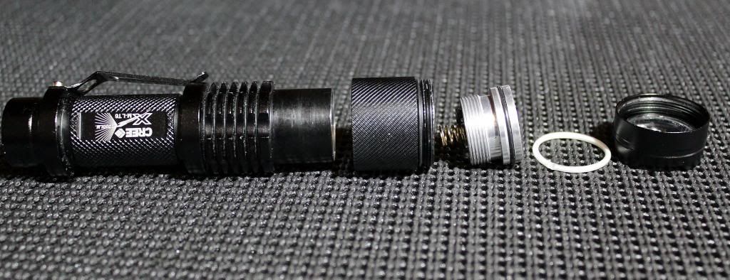
Just thought Id give a quick run down and mini tutorial of my attempt to mod my Sipik 98...
Well I started with an 18 mm thick copper rod drilled a couple of holes, cut it to length and inserted, or rather hammered") , it into the pill. Had to widen and drill out the pill a little first however. Be careful drilling copper; its quite soft and sticky and I ended up breaking 2 drill bits...I found the best way, was to go very slowly and clean the swarf from the bit every time it appeared.
, it into the pill. Had to widen and drill out the pill a little first however. Be careful drilling copper; its quite soft and sticky and I ended up breaking 2 drill bits...I found the best way, was to go very slowly and clean the swarf from the bit every time it appeared.
Re-flowing
Re-flowing is simply adding solder paste between two components to be soldered and heating. A thin layer of solder paste was applied to the top of the copper rod and a copper star (from BLF) placed on top. The rod was heated from the base with a heat gun, until solder paste started to bubble and change from milky to clear. I actually let it heat a couple of seconds past this stage and moved the copper bar to a block of Aluminium to cool.
I used solder because it is actually much better than any heat sink compound or grease at transferring the heat...(Solder is around 70 Wm-1K-1, where as most heat sink compounds are around 3 Wm-1K-1!!!)
The paste was applied to the contacts of the sink pad with a pin and the XM-L2 T6 chip was carefully aligned on the star and the rod + star again heated from underneath. You dont have to worry too much about alignment as the the solder paste sucks the emitter down onto the board when it starts to bubble.
Unfortunately, I put it all together before finding out that the LED wasn't working...So I had to reheat the whole assembly and carefully remove the emitter from the star. I say carefully, but I actually dropped it after I got it off the star and spent 1/2 hour looking for it on the floor. Id actually given up on that emitter and decided to sweep up and low and behold I found it, along with a lot of dust, turnings and crud... :tinfoil:
So re-flow attempt 2! After cleaning up the emitter, I added a load of flux and a tiny bit more paste to the sink pad contacts and tried once more..I tested the emitter as soon as it had cooled and this time it had worked!
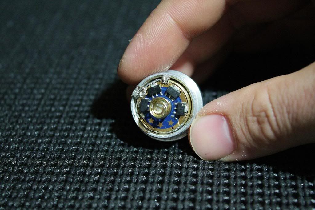
Assembly
I cut a piece of circuit board and glued it to the base of the rod. A spring was attached as a positive contact and the contact leads soldered. I picked up the negative path directly from the rod under the star. You will notice two holes drilled in the board instead of using the sides of the star for the wires. I had to do this as there was no room to drill holes at the side of the board... Anyway after a lot of trial and error (sanding, hammering, soldering and swearing) I got it all up and running! I was just tightening the pill and was one step away from finishing, when I slipped and my nail sliced through the dome...:wtf: Again and amazingly the emitter was still working, but the output had an ugly artifact.
Dedoming
The next day I decided to dedome it; my first attempt. A sharp razor blade was used to carefully cut away at the dome down to about 1 mm from the emitter surface. Here I was actually attempting a "partial dedome". I had read on BLF that one needs to polish it with a dremel after cutting and so tried that, but that didn't work so well as the dome actually became more opaque? :thinking: Deciding to test it anyway, I turned it on and the emitter began to smoke. Sh*t. I quickly turned it off and had a nice burnt spot in the centre of the dome. (need a pulling out hair emoticon here...:crackup") I guess a small piece of dremel-wheel-cloth or dust got on there somehow. Well the only thing left was to completely dedome it, so I heated it to (Im guessing 80 to 100 deg C) and carefully picked at it with the razor blade until it all peeled off. That bit worked really well and surprisingly the bond wires were still intact!
I guess a small piece of dremel-wheel-cloth or dust got on there somehow. Well the only thing left was to completely dedome it, so I heated it to (Im guessing 80 to 100 deg C) and carefully picked at it with the razor blade until it all peeled off. That bit worked really well and surprisingly the bond wires were still intact!
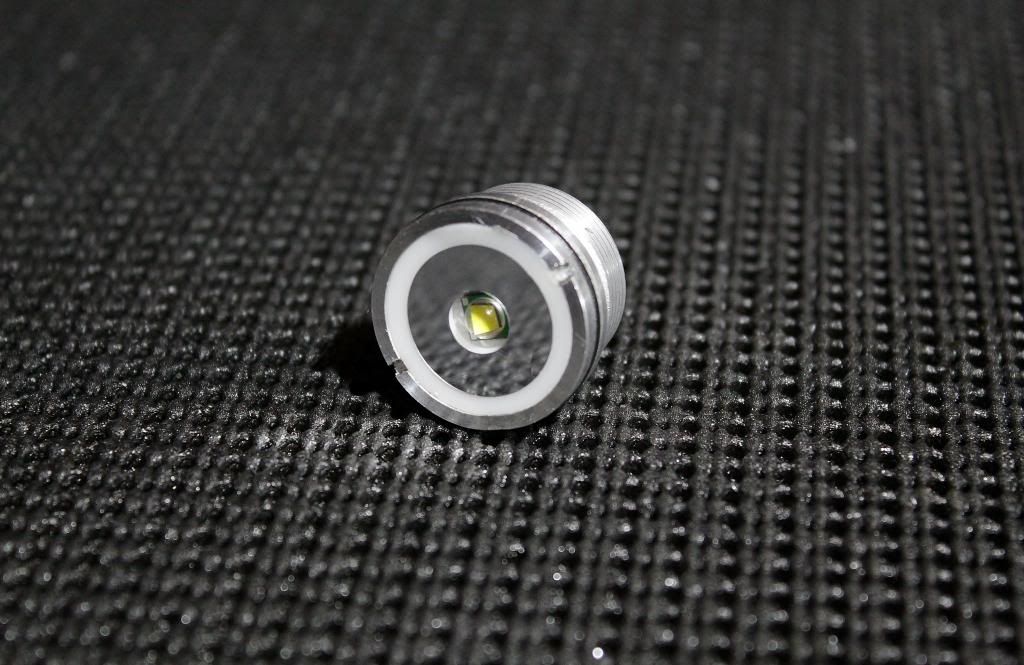
Result
After the dedoming the colour shifted to a yellow/white from a blue/white and is actually quite appealing. The difference in colour is only really noticeable however, if you compare it side by side to another domed emitter, otherwise it actually looks white.
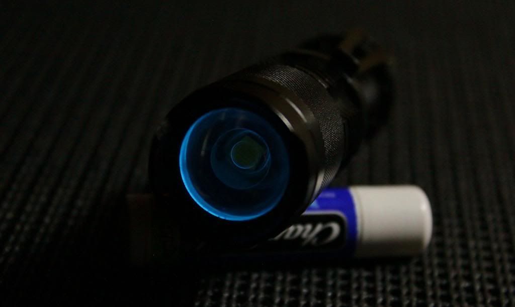
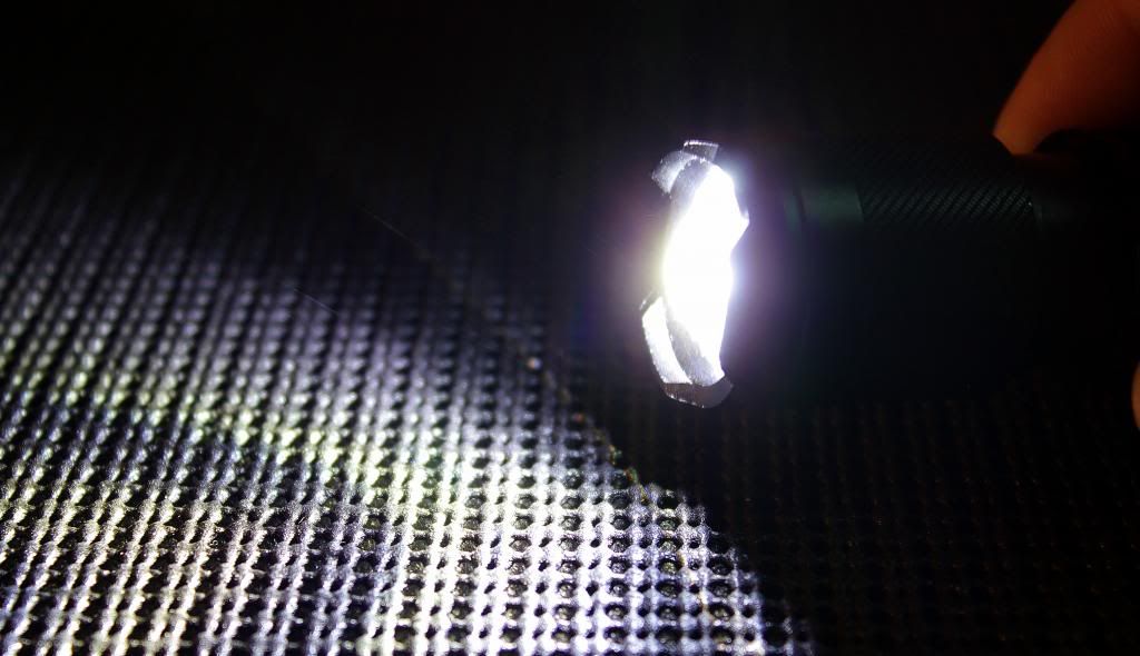
Its direct driven ie no driver, but due to the resistance of the current path, the diode is only pulling around 4 A!! Dont worry, that really is plenty and in the end I decided not to modify the switch or improve the contacts...Maybe I will later though! :eg: The light gets quite warm after a couple of mins so its not a practical work light, but works well as an intermittent search light or just a light to wow people as its ridiculously bright and great fun!
With the removal of the dome, the throw has also increased dramatically and I can now get a much smaller dot in throw mode!
All in all a fun if not chaotic build, but it worked out well in the end! :yh:
If anyone wants any more details on dedoming or re-flowing emitters just let me know! Hopefully I can also advise you on how not to do things!:crackup:
Pics below! :beer:
Well I started with an 18 mm thick copper rod drilled a couple of holes, cut it to length and inserted, or rather hammered
, it into the pill. Had to widen and drill out the pill a little first however. Be careful drilling copper; its quite soft and sticky and I ended up breaking 2 drill bits...I found the best way, was to go very slowly and clean the swarf from the bit every time it appeared.Re-flowing
Re-flowing is simply adding solder paste between two components to be soldered and heating. A thin layer of solder paste was applied to the top of the copper rod and a copper star (from BLF) placed on top. The rod was heated from the base with a heat gun, until solder paste started to bubble and change from milky to clear. I actually let it heat a couple of seconds past this stage and moved the copper bar to a block of Aluminium to cool.
I used solder because it is actually much better than any heat sink compound or grease at transferring the heat...(Solder is around 70 Wm-1K-1, where as most heat sink compounds are around 3 Wm-1K-1!!!)
The paste was applied to the contacts of the sink pad with a pin and the XM-L2 T6 chip was carefully aligned on the star and the rod + star again heated from underneath. You dont have to worry too much about alignment as the the solder paste sucks the emitter down onto the board when it starts to bubble.
Unfortunately, I put it all together before finding out that the LED wasn't working...So I had to reheat the whole assembly and carefully remove the emitter from the star. I say carefully, but I actually dropped it after I got it off the star and spent 1/2 hour looking for it on the floor. Id actually given up on that emitter and decided to sweep up and low and behold I found it, along with a lot of dust, turnings and crud... :tinfoil:
So re-flow attempt 2! After cleaning up the emitter, I added a load of flux and a tiny bit more paste to the sink pad contacts and tried once more..I tested the emitter as soon as it had cooled and this time it had worked!
Assembly
I cut a piece of circuit board and glued it to the base of the rod. A spring was attached as a positive contact and the contact leads soldered. I picked up the negative path directly from the rod under the star. You will notice two holes drilled in the board instead of using the sides of the star for the wires. I had to do this as there was no room to drill holes at the side of the board... Anyway after a lot of trial and error (sanding, hammering, soldering and swearing) I got it all up and running! I was just tightening the pill and was one step away from finishing, when I slipped and my nail sliced through the dome...:wtf: Again and amazingly the emitter was still working, but the output had an ugly artifact.
Dedoming
The next day I decided to dedome it; my first attempt. A sharp razor blade was used to carefully cut away at the dome down to about 1 mm from the emitter surface. Here I was actually attempting a "partial dedome".
I had read on BLF that one needs to polish it with a dremel after cutting and so tried that, but that didn't work so well as the dome actually became more opaque? :thinking: Deciding to test it anyway, I turned it on and the emitter began to smoke. Sh*t. I quickly turned it off and had a nice burnt spot in the centre of the dome. (need a pulling out hair emoticon here...:crackup I guess a small piece of dremel-wheel-cloth or dust got on there somehow. Well the only thing left was to completely dedome it, so I heated it to (Im guessing 80 to 100 deg C) and carefully picked at it with the razor blade until it all peeled off. That bit worked really well and surprisingly the bond wires were still intact! Result
After the dedoming the colour shifted to a yellow/white from a blue/white and is actually quite appealing. The difference in colour is only really noticeable however, if you compare it side by side to another domed emitter, otherwise it actually looks white.
Its direct driven ie no driver, but due to the resistance of the current path, the diode is only pulling around 4 A!! Dont worry, that really is plenty and in the end I decided not to modify the switch or improve the contacts...Maybe I will later though! :eg: The light gets quite warm after a couple of mins so its not a practical work light, but works well as an intermittent search light or just a light to wow people as its ridiculously bright and great fun!
With the removal of the dome, the throw has also increased dramatically and I can now get a much smaller dot in throw mode!
All in all a fun if not chaotic build, but it worked out well in the end! :yh:
If anyone wants any more details on dedoming or re-flowing emitters just let me know! Hopefully I can also advise you on how not to do things!:crackup:
Pics below! :beer:
Last edited: