Welcome to Laser Pointer Forums - discuss green laser pointers, blue laser pointers, and all types of lasers

LPF Donation via Stripe | LPF Donation - Other Methods

Links below open in new window

ArcticMyst Security by Avery

X-Drive X-Boost

Joined
Jul 10, 2015
Messages
9,907
Points
113
Dumb question here.

The SXD V3 Fixed without the pot will take 3 LI-MN cells won't it?

They float at 4.17 but will sag a bit under load.

I will need 3.5A, 4.0A, and 4.5A drivers and want to use 3 cells to extend runtime without sagging below 6.8v

I can't get MX-900's anymore so I'm going to switch to 4 x C cell maglites and make a spring/button spacer to run 3 x 26650's

I will be driving Gballs ,7A75's, 07E's and 44's
 
Last edited:


Joined
Feb 11, 2013
Messages
304
Points
28
I don't know if I'm missing this, but what is the maximum input voltage for the 5000ma SXD-V3? It says the input range for other X-Drives but not the V3.
 
Joined
Mar 5, 2015
Messages
1,336
Points
113
I'm not sure about the SXD but I asked similar question to Jordan the other day, not sure if this helps just pm him.

can I use 3 14500 batts for a total of 12.6v with this 1.8a fixed Buck driver!

You can but it may not give a very long cycle before the driver shuts down for cooling.:)

Reson I ask is you list voltage of xdrive at 6-9v Or is it 3.7-16v just want to double check bro, I know I'm not getting full power with 2/14500!

Yea I do that as it has to be 6-9V so you can run the driver for 90 on 30 off with appropriate heatsinking for the module. If you go to 12V it won't hurt anything but may only run for 20-30 seconds on 30 off.
 
Joined
Feb 11, 2013
Messages
304
Points
28
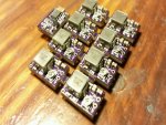
That's kind of what I thought. I just got a order of these SXD-V3 drivers today. I love the way they look when they're still connected. It brings out the nerd in me.
 

Attachments

  • 20160304_190705-800x600.jpg
    20160304_190705-800x600.jpg
    136.4 KB · Views: 125

DTR

0
Joined
Jun 24, 2010
Messages
5,684
Points
113
Both the X-drive and SXD can handle up to 16V input. Driving a 445nm load you need at least 6V with the X-drive and 6.5V with the SXD. On the 1.8A and 2.4A X-drive if you don't plan to sink them and want to keep the 120 second(1.8A) 90 second(2.4A) on 30 off duty cycle you would want to stay under 9V as you go over that the duty cycle of the unsinked drivers go down. If you sink the driver this does not matter you can run the driver continuously at any current with up to 16V. Still I do think staying around 12V or under is best as the higher the difference between the load and the input voltage the more heat you create that your build has to deal with.:beer:
 

Pman

0
Joined
Nov 28, 2012
Messages
4,447
Points
113
I had no idea they could handle that much voltage. Hmmm, options options options. Me like.
 
Joined
Jul 10, 2015
Messages
9,907
Points
113
They will take 3 cells in series, that's great.
Yes that will help runtime between charges in my heavier builds.

I bought some IMREN 5500 MaH IMR's that said 22A / 60A and even though the Efest are rated 40A / 60A I thought since they are IMR they should not sag too much because they claimed to be the Efest Killer, Well these sag from a full charge to 3.75 just like old NCR18650B into a 1 ohm load where the Efest IMR hold 4.0 volts at 4.0 amps from a full charge into a 1 ohm load, even the LG INR 18650's sag way less.

These 26650 IMREN 5500 Mah are a disappointment for the high price, they should run my flashlight longer but for high drain they are not the way to go.
 
Joined
Jul 9, 2009
Messages
177
Points
28
Got a question, fellas. I just received the sxd v3, 4.5A fixed from DTR. I soldered a nub44 and heatsinked the driver fired it up using a 2s lipo and it worked great. I needed to desolder the diode leads on the driver to rearrange the drivers placement in the host. I resoldered the leads when done, applied power, and all I got was a very dim output. I desoldered again and tested the diode with my power supply, the diode is fine. Soldered again, same dim output.

I'm just wondering if there may be a range solder jumper between resistors that I may have accidently melted on this driver while resoldering. I see that option at pyros post at the beginning of this thread, it is very similar but doesn't look like the same driver, the components are arranged slightly different.

One more question, when it was working, even though I had the 8 pin chip heatsinked with a substantial heatsink, the inductor on the opposite side still got very hot. Is that normal? Should I heatsink the inductor in addition to the 8 pin?

Thanks in advance!:)
 
Last edited:
Joined
Dec 15, 2014
Messages
6,783
Points
113
hi Barth
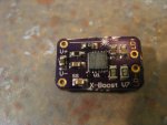
To achieve the second rangoon the SXD V7 driver you have to bridge the twi resistors #330 and #210 together theses are the two right under were it says V7 on the driver in the pic. But i don't think thats your issue here. An unbridged driver wouldn't make the diode dim out, you would just get a lower output reading.So it's another problem in my opinion.

Rich:)
 

Attachments

  • IMG_1636.JPG
    IMG_1636.JPG
    167.4 KB · Views: 131
Joined
May 4, 2009
Messages
5,443
Points
113
Yes it dose sound like maybe you de-soldered something, can you take a close up picture of both sides of the driver ?

Jeff...


Got a question, fellas. I just received the sxd v3, 4.5A fixed from DTR. I soldered a nub44 and heatsinked the driver fired it up using a 2s lipo and it worked great. I needed to desolder the diode leads on the driver to rearrange the drivers placement in the host. I resoldered the leads when done, applied power, and all I got was a very dim output. I desoldered again and tested the diode with my power supply, the diode is fine. Soldered again, same dim output.

I'm just wondering if there may be a range solder jumper between resistors that I may have accidently melted on this driver while resoldering. I see that option at pyros post at the beginning of this thread, it is very similar but doesn't look like the same driver, the components are arranged slightly different.

One more question, when it was working, even though I had the 8 pin chip heatsinked with a substantial heatsink, the inductor on the opposite side still got very hot. Is that normal? Should I heatsink the inductor in addition to the 8 pin?

Thanks in advance!:)
 

Pman

0
Joined
Nov 28, 2012
Messages
4,447
Points
113
Doesn't sound good. If it's a fixed driver why would he need to bridge anything when it was sold as a 4.5A? Seems like that would have already been done.
 
Last edited:
Joined
Mar 5, 2015
Messages
1,336
Points
113
Yep when Jordan sell the fixed SXDs he does the bridging himself if needed,
But that doesn't help his issue!

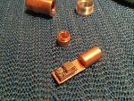
On the side you need to sink all the parts are the same height, it's easier to just thermal paste the whole driver,
 

Attachments

  • 1462707394.9191.jpg
    1462707394.9191.jpg
    647.6 KB · Views: 124
Last edited:

Pman

0
Joined
Nov 28, 2012
Messages
4,447
Points
113
Yeah, I know bad;)
For whatever reason unless those solder joints are bad you will likely have to buy another driver unless you can trace out the connections at those solder joints or have another driver to compare.
 
Joined
Jul 9, 2009
Messages
177
Points
28
I fixed the problem! ;) I put some flux on each side of the board and reflowed all the components with my hot air rework station. Soldered everything, applied power and voila, bright beam!

Guess a component had a crappy solder joint after I desoldered the first time.

Thanks for everybody's input! Don't forget it's mother's day today!:thanks:


Top