Welcome to Laser Pointer Forums - discuss green laser pointers, blue laser pointers, and all types of lasers

LPF Donation via Stripe | LPF Donation - Other Methods

Links below open in new window

ArcticMyst Security by Avery

Would anyone be willing to give me a couple minutes of help with a circuit?

rhd

0
Joined
Dec 7, 2010
Messages
8,475
Points
0
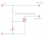
I'm having trouble with the implementation of a MOSFET into a circuit that I otherwise know works properly.

If anyone is willing to glance at it and give me their thoughts, it would really be helpful. I'd be happy to toss a few fractions of a bitcoin in your direction as a thank you, lol ;)
 
Last edited:


NKO29

0
Joined
Jun 6, 2013
Messages
861
Points
28
Re: What anyone be willing to give me a couple minutes of help with a circuit?

What is the particular Mosfet in question? Pics of the circuit possible?
 

rhd

0
Joined
Dec 7, 2010
Messages
8,475
Points
0
Re: What anyone be willing to give me a couple minutes of help with a circuit?

What is the particular Mosfet in question? Pics of the circuit possible?

Sure - and thanks.

This is the MOSFET:
http://www.diodes.com/datasheets/DMN2065UW.pdf

This is my circuit:
attachment.php


When I close the circuit (trigger the switch) the MOSFET burns itself out in a few seconds.
 

Attachments

  • circuit.png
    circuit.png
    12.2 KB · Views: 329

NKO29

0
Joined
Jun 6, 2013
Messages
861
Points
28
Re: What anyone be willing to give me a couple minutes of help with a circuit?

I'm no electronics expert, so i may be totally wrong, but do you have your driver's negative side connected to the mosfet's DRAIN? even though it's the negative side, it is still a SOURCE for the mosfet... Just a thought, may be wrong :p
 

rhd

0
Joined
Dec 7, 2010
Messages
8,475
Points
0
Re: What anyone be willing to give me a couple minutes of help with a circuit?

I'm no electronics expert, so i may be totally wrong, but do you have your driver's negative side connected to the mosfet's DRAIN? even though it's the negative side, it is still a SOURCE for the mosfet... Just a thought, may be wrong :p

Yes, it's connected to the drain.

I basically followed this circuit:
571px-Mosfet_n-ch_circuit.svg.png

http://upload.wikimedia.org/wikiped...circuit.svg/571px-Mosfet_n-ch_circuit.svg.png

But instead of the load being a resistor+diode, the load is another circuit (a driver)
 
Joined
Sep 20, 2013
Messages
17,426
Points
113
Re: What anyone be willing to give me a couple minutes of help with a circuit?

rdh, you have a simple switch circuit here and don't quite understand why you are using this circuit for a laser driver. It is an N channel enhanced mode MOSFET with the gate connected through a switch to the Vcc. This will make a switch, but nothing more. I did notice you have a schottky diode across the low side of the LD and ground. That won't give you any regulation though. There are probably dozens of ways to set this up to regulate the current flow, but can't do it for you this late. I will see what I can do tomorrow if you like.
 
Last edited:

rhd

0
Joined
Dec 7, 2010
Messages
8,475
Points
0
Re: What anyone be willing to give me a couple minutes of help with a circuit?

This will make a switch, but nothing more. I did notice you have a schottky diode across the low side of the LD and ground. That won't give you any regulation though. There are probably dozens of ways to set this up to regulate the current flow, but can't do it for you this late. I will see what I can do tomorrow if you like.

That's all I'm looking for - a switch. Not current reg. I'm not looking to build a driver here, just a switch ;)

You'll see that there are outputs labelled DRIVER- and DRIVER+ (they're not labelled LD). Imagine that those are the inputs to... a Flexdrive, or an X-Drive, or whatever you might be using for current reg.

This isn't a driver thread, just a switch thread. I can't see where I've gone wrong - this should work as a switch, no?
 
Last edited:
Joined
Sep 20, 2013
Messages
17,426
Points
113
One problem that jumps out at me is the sum total of all your current, and by virtue all the power dissipated through your driver will go through your MOSFET. You may want to check the power dissipation of your entire circuit and see if your MOSFET can handle it for a lengthy duration. I'm assuming that for purposes of scale you are not using a heat sink. This is where I would start to look.
 
Last edited:

rhd

0
Joined
Dec 7, 2010
Messages
8,475
Points
0
One problem that jumps out at me is the sum total of all your current, and by virtue all the power dissipated through your driver will go through your MOSFET. You may want to check the power dissipation of your entire circuit and see if your MOSFET can handle it for a lengthy duration. I'm assuming that for purposes of scale you are not using a heat sink. This is where I would start to look.

That's a good thought. I don't think that's the problem though.

Continuous drain current on this MOSFET is 2.3 to 2.8 A, and I was only running at ~1.5 A. Plus (and this is really the key) the MOSFET immediately burned up, and the circuit never powered up even for a second. If I was above current/heat dissipation tolerances (which I wasn't), it wouldn't immediately burn up. But, as mentioned, this MOSFET can handle the current I was feeding it, so I don't think that's the problem.

Could there be an issue powering the Gate with 8V ?

The Gate threshold voltage on this MOSFET is really low (like 1.5V I think). However, the Gate-to-Source voltage is 12V, so I thought I was fine.
 
Joined
Sep 20, 2013
Messages
17,426
Points
113
rhd, it occurred to me that if you are trying to push all your power through this MOSFET you might be better off by using a DMOS instead of a CMOS FET. The DMOS is a double diffused metal oxide semiconductor as opposed to a complimentary metal oxide semiconductor and are used in circuits that need to displace a lot of power, which usually shows up in the form of heat. Look into it and see if one of these might be what you are looking for. Your gate set up looks fine to me for a switch. I don't think your problem lies there.
 
Last edited:

NKO29

0
Joined
Jun 6, 2013
Messages
861
Points
28
Looking at the circuit you made, and the one in wikipedia i can see that you've probably connected the Drain and Source the wrong way
2ldvwhc.png
 

rhd

0
Joined
Dec 7, 2010
Messages
8,475
Points
0
Looking at the circuit you made, and the one in wikipedia i can see that you've probably connected the Drain and Source the wrong way
2ldvwhc.png


The diode in that first photo is the LOAD, it's actually an LED. It is part of the circuit. It's not part of the MOSFET.

The diode you're circled in my design is just the MOSFET's internal diode. It is not part of my circuit, it's part of the MOSFET.
 

NKO29

0
Joined
Jun 6, 2013
Messages
861
Points
28
Ah... But it still shows what way the current is flowing? The 2 internal diodes would not let that current pass would they? Just my opinion on this I can't see anything else that could be wrong :p do you have any spare mosfets to play with?
 

rhd

0
Joined
Dec 7, 2010
Messages
8,475
Points
0
Ah... But it still shows what way the current is flowing? The 2 internal diodes would not let that current pass would they? Just my opinion on this I can't see anything else that could be wrong

That's the point of the internal diode. It's reversed biased. The current doesn't flow over the MOSFET's internal diode, it flows over the MOSFET. I think it can safely be ignored - it's just there.
 
Joined
Sep 20, 2013
Messages
17,426
Points
113
The internal diode is a schottky diode and the drain is connected to the load while the source is connected to ground. This is connected properly to make a switch. I still think the problem is in the load. You may want to try a load resistor to limit the current. You can't see the initial load at the instant of conduction and that may be higher than the MOSFET's rating.
 

rhd

0
Joined
Dec 7, 2010
Messages
8,475
Points
0
I don't want to limit current into a drivers input though. If that were the solution, then it would negate the benefit of a MOSFET's efficiency. It just seems wrong in principle to have to use a current limiting resistor on the input to a high efficiency switching current regulator (or whatever type of driver I power with this circuit).
 
Last edited:


Top