Welcome to Laser Pointer Forums - discuss green laser pointers, blue laser pointers, and all types of lasers

LPF Donation via Stripe | LPF Donation - Other Methods

Links below open in new window

ArcticMyst Security by Avery

Will this test load work?

jakeGT

0
Joined
Oct 29, 2010
Messages
3,532
Points
0
go to bottom of page, im almost done with my test load just a few more questions
test%20load01.jpg
 
Last edited:


jakeGT

0
Joined
Oct 29, 2010
Messages
3,532
Points
0
Merged three consecutive posts

haha nevermind, i found my answer and your just gonna send me one anyways jeff!

it was this schematic for setting up a phr, i just wanted to know if it would work for a microboost drive, and i just want to change my driver from 1.37A to 500mA for a 12x diode, and use one single 18650 3.7/4.2v
test%20load01.jpg

rog8811's schematic from his website

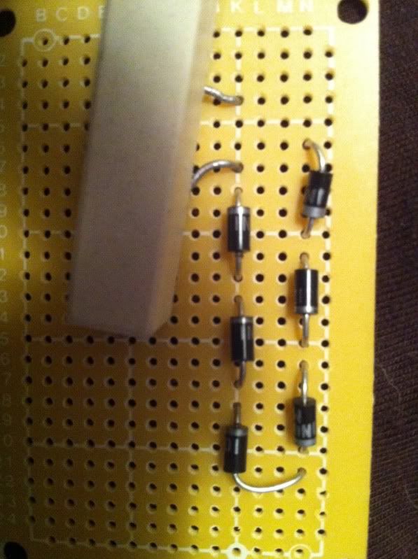
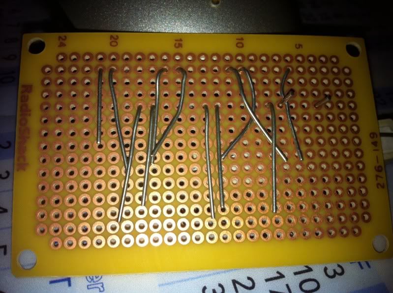
okay, so here is what i have so far, please let me know if there are any errors

f362531c.jpg


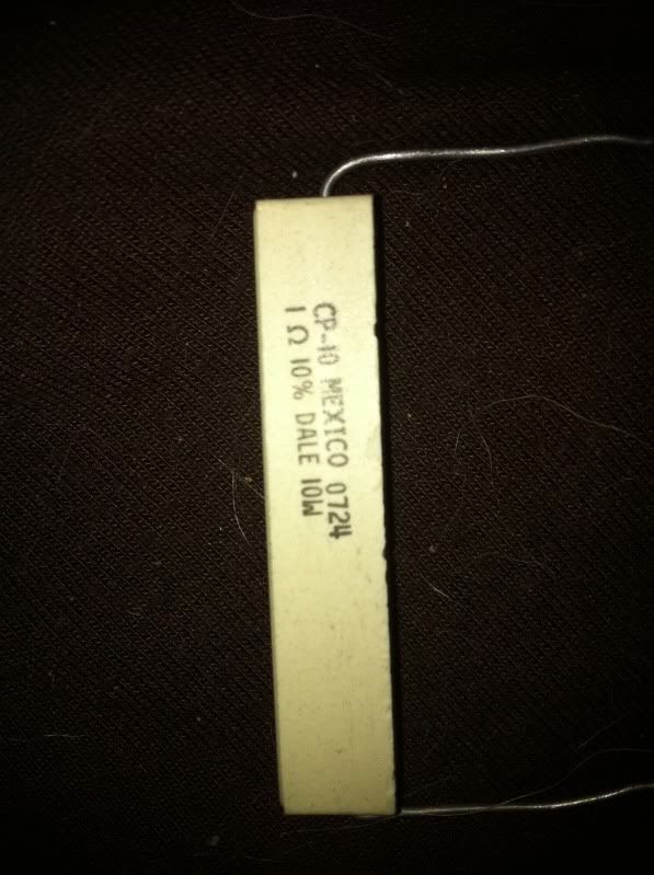
The big block looking thing is a 1ohm resistor, that i got at radioshack, will this work even though its not a little tiny one like the others?

5d066f0f.jpg


61fbbb4b.jpg


and i just solder each two that are next to each other with a solder bridge to connect them correct?
 
Last edited by a moderator:

anselm

0
Joined
Nov 22, 2010
Messages
2,448
Points
0
Yes, but first trim the leads nice and short.

That resistor is just fine, but it says 10%, so it can be anything 0.9~1.1Ohm,
But I doubt you could accurately measure it with a normal DMM with 0.1V resolution.
In any case, put the DMM on its lowest setting for resistance, I think 200Ohm, touch
the probes directly one to each other and see what it reads.

Then subtract this value from whatever you measure when you put the probes on the resistor.
 

jakeGT

0
Joined
Oct 29, 2010
Messages
3,532
Points
0
Merged two consecutive posts

how about where it says on this picture "connections to test for 803t blu-ray"
do i just solder wires to the actual resistor wires coming out the back? or does it have to touch the copper part on the back of the veroboard also?

and also, this is my multimeter, which i just got yesterday still new to all the settings,i put it on ohms, and it said 1.1 and 1.2 when it settled down and i had my hands steady

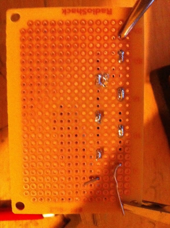
also here is what i have so far, will the little "mistake" be harmful to it since theres nothing in that row and the solder blobs are not connecting at all?

dd3c7e23.jpg
 
Last edited by a moderator:

anselm

0
Joined
Nov 22, 2010
Messages
2,448
Points
0
plus from the driver -> the dangling lead of the first diode,
minus from the driver -> the dangling lead of the resistor

and your done.

that solder mishap doesn't matter.
 

jakeGT

0
Joined
Oct 29, 2010
Messages
3,532
Points
0
okay so just solder them to the dangling lead out of the back of the test load anywhere is fine correct?

and also can i just keep my driver hooked up in my host, pop the battery in and turn it on ?

also also just to make sure, i just touch the sides of the resistor with my dmm, doesn't matter which side to which side?

and also, what do i set my dmm to when i have it all hooked up?

also also also,(haha) should i solder the last leg of the resistor and the diode i havent soldered yet also or just leave the legs dangling without soldering them in place?
 
Last edited:

jakeGT

0
Joined
Oct 29, 2010
Messages
3,532
Points
0
so it would work just to turn the driver alot to counter clock wise? lol

edit: but still, i would like to learn how to test load and what not
 

jayrob

0
Joined
Sep 21, 2007
Messages
9,862
Points
113
I think the image that you posted in the first post answers all of the questions you are asking??

test%20load01.jpg


One thing you have to watch out for, is that these silicon diodes are not meant to handle the kind of load that we are setting these days...

I have found that they will last, and not get damaged if you use a 1 second test. Then make adjustment, Then test again for 1 second, and so on...

This is 'trial and error', and maybe a little tricky to get your desired adjustment, but at least you won't fry your test load...
 
Joined
Jan 14, 2011
Messages
424
Points
0
Hi Guys,
New kid on the block and I may have missed something, BUT!!! If you set your DMM to measure AMP/mAMP.s and hook it up in parallel with the load resister (as shown), won't you smoke your DMM? Shouldn't the DMM be hooked up in series with the driver (DMM neg (-) Black to the driver LD-, DMM pos (+) Red to the open end of the load resistor (1Ohm) and set to read current)??
 
Joined
Jan 14, 2011
Messages
424
Points
0
Oops, sorry. I did not READ the comments at the bottom of the figure (set DMM to read mV (not mA)). My BAD. But,, O.K. ,, why read mV and apply Ohm's law when you have a DMM and can read mA.s directly?
 
Joined
May 4, 2009
Messages
5,443
Points
113
You may not want to use that resistor as it is a wire wound type, you can not use a wire
wound type as they have INDUCTANCE and the driver may be dammaged or you may not
get a true reading most likely it can dammage the driver.
you need a NON-INDUCTANCE type resistor :tsk:
best to look for noninductive, flame proof 1 ohm 1% 1W or 2W or 3W be ready to pay about $3.00-$6.00
 
Last edited:

anselm

0
Joined
Nov 22, 2010
Messages
2,448
Points
0
You can get away with measuring with the DMM in series and in amp measuring mode.
I guess it's mostly about the convenience and security (for the driver) to have a complete
circuit to begin with, not relying on your DMM-probes to complete the circuit...
 
Joined
May 4, 2009
Messages
5,443
Points
113
WHAT :wtf: so your telling him he can just touch the leads of his VOM between the laser diode and the driver, with out making solder connections :thinking: are you trying to get him to kill his laser diode and his driver :thinking:

This is not very good advice and I would not listen to it !!!


You can get away with measuring with the DMM in series and in amp measuring mode.
I guess it's mostly about the convenience and security (for the driver) to have a complete
circuit to begin with, not relying on your DMM-probes to complete the circuit...


Top