

- Joined
- Dec 20, 2007
- Messages
- 119
- Points
- 0
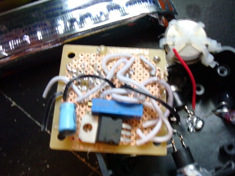
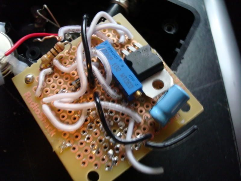
I am using a senkat diode.
A 10k multiturn pot
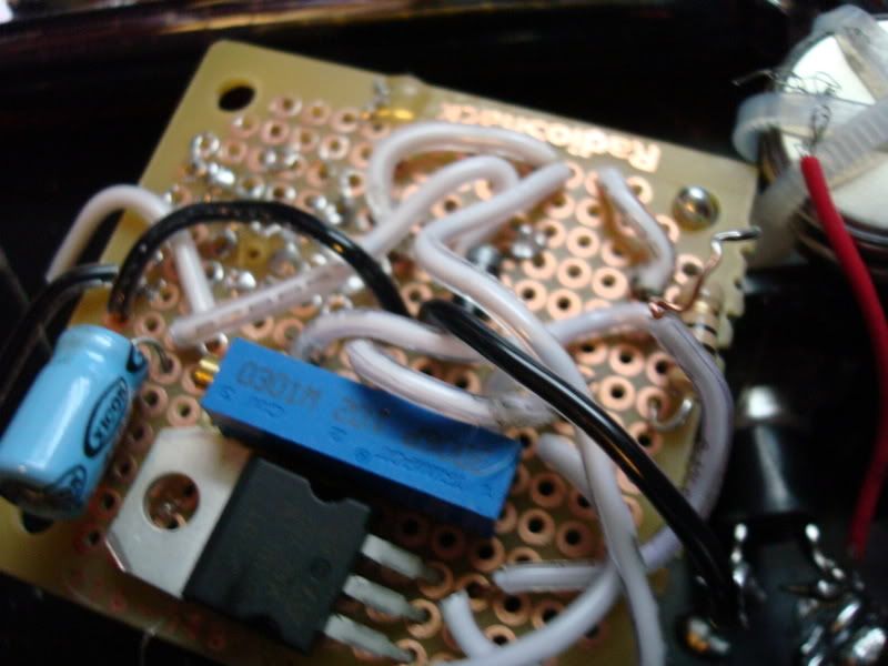
LM317T + volt Reg
10 OHM resistor 1/2 watt
1N4001 silicone diode
47MFD 35VDC capacitor
two CR2032 energizer batteries each rated for 3v, not used before
And a momentary switch in between
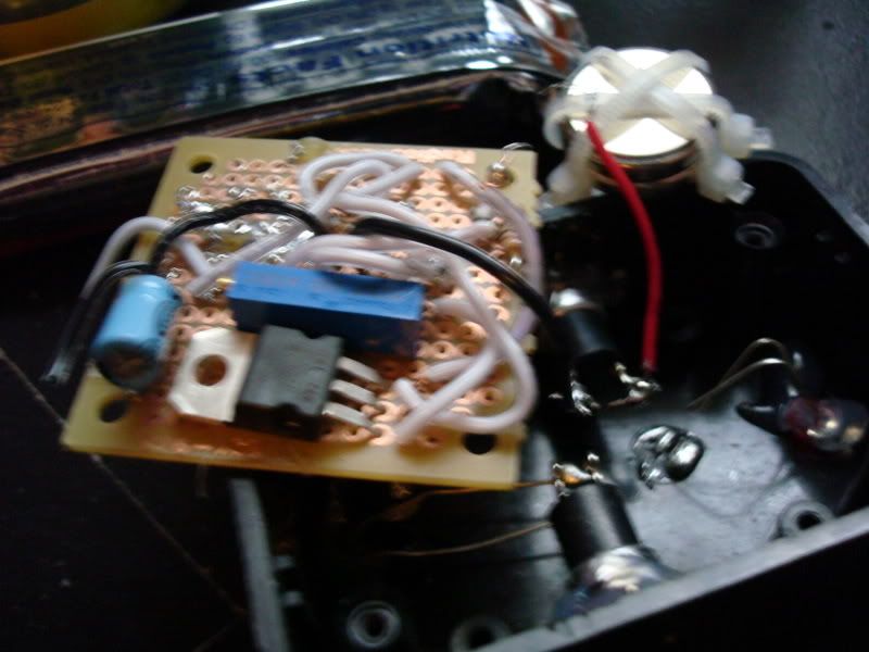
I have an analog multimeter but I cannot get it to work...
I hooked it all up according to daedal's thread and was greatly releived to see my laser come to life!
It was a VERY dim light so I turned my pot, nothing happened... turned most possible both ways, still the dot was extremely dim.
I tried it with a 10ohm 1/4 watt resistor and still same thing
If needed I have a 1K multiturn pot here if you guys think I should try it.
I got my parts from radioshack btw.
Here are some pics
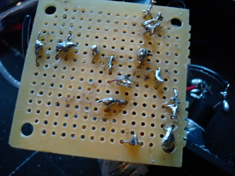
Any help is greatly appriciated, if I need different parts what are they?
A 10k multiturn pot
LM317T + volt Reg
10 OHM resistor 1/2 watt
1N4001 silicone diode
47MFD 35VDC capacitor
two CR2032 energizer batteries each rated for 3v, not used before
And a momentary switch in between
I have an analog multimeter but I cannot get it to work...
I hooked it all up according to daedal's thread and was greatly releived to see my laser come to life!
It was a VERY dim light so I turned my pot, nothing happened... turned most possible both ways, still the dot was extremely dim.
I tried it with a 10ohm 1/4 watt resistor and still same thing
If needed I have a 1K multiturn pot here if you guys think I should try it.
I got my parts from radioshack btw.
Here are some pics
Any help is greatly appriciated, if I need different parts what are they?


") amk is absolutely correct, no where near enough ma out of button cells to drive a red and the voltage will sag under load.
amk is absolutely correct, no where near enough ma out of button cells to drive a red and the voltage will sag under load.