Welcome to Laser Pointer Forums - discuss green laser pointers, blue laser pointers, and all types of lasers

LPF Donation via Stripe | LPF Donation - Other Methods

Links below open in new window

ArcticMyst Security by Avery

Which is better?

Joined
Jan 12, 2008
Messages
3,290
Points
83
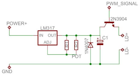
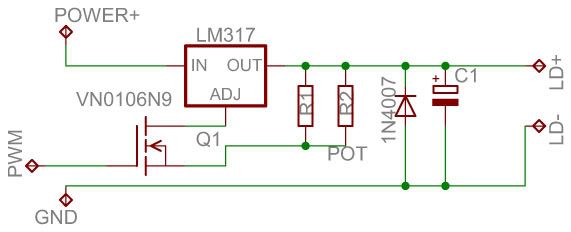
If I need to make a 0-240 ohm potentiometer out of a higher value: either 300 or 500 ohms, and connect a resistor in parallel with it: either 1200 or 470 ohms, which is better? I want it so be very smooth.

pots-1-1-1.jpg


Thanks! :)


Joined
Sep 8, 2008
Messages
182
Points
0
Either way it won't be linear. But the 300 ohm pot would work better...

To see why do the math for the halfway point of the pot's wiper for each scenario. ;) You'll see that you don't get 120 Ohms either way. (Not even close)

cheers,
kernelpanic
 
Joined
Dec 26, 2007
Messages
6,129
Points
0
I'd go with the second solution, as you can get a higher control over the value of the resistance because the dial goes from 0 to 300 ohms.
 
Joined
Sep 8, 2008
Messages
182
Points
0
FireMyLaser said:
So is there a better way?

Niko is right but there's one caveat-

If linearity isn't important then the 300/1200 combo will work best. If it is, then just use the 300 and don't turn it past 4/5. Here's why-

Wiper
Position Linear 300/1200 500/470
0 0 0 0
1/4 60 71 99
1/2 120 133 163
3/4 180 189 209
1 240 240 240

Using a parallel resistor pushes the adjustment to one side of the pot. With 500/470 with the wiper at halfway you're at 163 ohms instead of 120. 300/1200 is closer at 133. For some circuits this won't matter. For some it will.

Hope this helps,
kernelpanic
 
Joined
Jan 12, 2008
Messages
3,290
Points
83
Maybe I should explain what I want to make. I have the DX 35mW module which will go into my RGV labby http://www.dealextreme.com/details.dx/sku.10004

It can operate between 3-6V, max 480mA (at 3V it has a minimum output). I want to add a panel-pot so I can vary the output 0-100%, and a trim-pot so It can be tuned to a nice white.

The pot on the board seems to do nothing, so I was thinking maybe this circuit will work?

http://ourworld.compuserve.com/homepages/Bill_Bowden/page12.htm

This should represent R2
pots-2-1.jpg


IDK, it's so complicated, I hate it! :-/
 
Joined
Sep 8, 2008
Messages
182
Points
0
That'll work. Make sure you use 1/4 watt parts as you've got around 1/8 watt going through constantly at 6v. If you've got only the 300 ohm pot, then do-

resistor- 47 ohms
trimmer- 100 ohms
pot- 300 ohms.

That'll get you close with the trimmer centered while still giving you linear response for your controls. (Also make sure to use linear pots/trimmers rather than logarithmic.)

Or you can use a 120 ohm resistor for R1 (the 'sense' resistor) and do-

resistor - 56 ohm
trimmer - 100 ohms
pot - 300 ohms

That wil put you at EXACTLY 6V at the top end and at 2.875V on the low end with the trimmer at 100 ohms.

Don't go higher than 120 ohms for R1 as the LM317 needs to see 10mA there. But any value from 80-120 ohms can be used with 1/4 watt parts to make the pot you happen to have fit. ;)

Hope this helps.

Cheers,
kernelpanic

[edit] Basically I'm saying, skip the bypass idea and tweak the other values to make the 300 ohm pot work... Non-linear response there in that circuit will be a pain. All of the adjustment will be at the bottom of the pot.[/edit]
 
Joined
Jan 12, 2008
Messages
3,290
Points
83
Thanks allot, it definitely helps! +1

Now, what if I'd just trash the existing board and replace it with a ddl style driver? Would that work better? It's definitely easier, ohm's law, add some pots, 10 to 480mA?
 
Joined
Sep 8, 2008
Messages
182
Points
0
FireMyLaser said:
Thanks allot, it definitely helps! +1

Now, what if I'd just trash the existing board and replace it with a ddl style driver? Would that work better? It's definitely easier, ohm's law, add some pots, 10 to 480mA?

That's doable too if your brave enough to de-solder your 808nM diode. (I'm not...)

Otherwise either option I suggested above will work. The first will go a little higher than 6V with the trimpot at 100 ohms. The second maxes out at 6v exactly to prevent overdriving the module.

cheers,
kernelpanic
 
Joined
Jan 12, 2008
Messages
3,290
Points
83
Ok I see. I think I can do that tho.

I made a sketch on the layout and added a 9V-regulator (the top one) so it impossible to put put more than 6V.
3-6Vreg.jpg

The green dots are for the panel pot.


What values on the caps should I use? All I got is harvested stuff, mostly electrolytic and ceramic, does it have to be tantalum?. :-/


EDIT: I forgot to add that I will also use PWM on all this, will the caps interfere??
 
Joined
Sep 8, 2008
Messages
182
Points
0
I forgot to add that I will also use PWM on all this, will the caps interfere??

O.K. Now you're beyond the LM317. It's meant to be a voltage regulator. If you're only talking about hundreds of cycles per second PWM (i.e. using PWN to turn colors on or off) you can get away with it. But if you want to smoothly blend or modulate beam strength, I'd try something different. Dr. Lava has a driver with TTL. It won't interfere with the module's driver as it's not switching. But you can also use a mosfet/op-amp driver to supply the desired voltage and also modulate the input. The circuit has a rise time of around 50ns. And I have no idea how long it takes for the DPSS module to reach threshold and start putting out green. (That is most probably the limiting factor.) Perhaps one of the more experienced members could shed some light?  :-? But a modulated current sink would do the trick for your purpose. If you're interested I'll draw up a schematic you can look at. (Was already thinking about that one...)

cheers,
kernelpanic
 
Joined
Jan 12, 2008
Messages
3,290
Points
83
Man its getting way complicated...
I don't know how many Hz it runs at, maybe 100, I can see the pulses when I use a LED and scan my eyes around.

I'm gonna connect it like this:

12V --> PWM circuit --> 3-6V regulator --> laser.

The PWM-circuit is a LED-dimmer/motor speed control kit which uses the 555-timer
 
Joined
May 17, 2009
Messages
7
Points
0
I am also thinking of modulating diodes for colour mixing, would pulsing the current damage the diode ?
as in this circuit ?

This is to be used for the R,G and V laser diodes,
pwmlaserdriver.jpg


Is there any different driving methods that I need to use for a green diode (actually a DPSS 50mW green , removed from the original driver)
 
Last edited:
Joined
May 17, 2009
Messages
7
Points
0
From the green DPSS laser topic

It is possible to change the pump diode in a green pointer, but not with a DVD burner diode. It requires an 808nm diode to make the crystals produce green.

Depending on how fast you want to modulate, you can modulate the supply to the LM317, but special cicuitry id required to modulate directly at the diode. If you use the circuit you've provided, you might blow the diode due to the fact that the signal will not be 100% clean. The signal that reaches the diode must be clean with absolutely no overshoot. You'd need to add filter circuitry after the transistor to make sure that the signal is clean, but the filter needs to be specially designed so that you can modulate at a high rate of speed.

I suggest you to use a mosfet, or modulate the adj pin of the LM317, instead ..... more safe


I have redone the circuit with a MOSFET... I will have to wait for my diodes to arrive before I will be able to test it.., R,G,V on their way...

Any comments welcome.. :p

Once I get all this working I will post the full circuit diagrams and pcb layouts I used, If annyone is interested..

pwmlaserdriver_2.jpg
 
Joined
Nov 7, 2008
Messages
5,725
Points
0
That circuit looks OK to me.. Your overall speed might still be slightly limited by the protection capacitor across the diode, but unless you're going to be using this system in a laser scanner or something, I wouldn't worry. You might still be able to get a few kHz out of it.

I highly recommend viewing the output signal with an oscilloscope before you attach a diode. (If you don't have a scope, here's one for $50US)

OOPS.. they're sold out.. try here. It's the same thing..
 
Last edited:


Top