Welcome to Laser Pointer Forums - discuss green laser pointers, blue laser pointers, and all types of lasers

Buy Site Supporter Role (remove some ads) | LPF Donations

Links below open in new window

FrozenGate by Avery

two drivers in parallel to make 1.8a?

Joined
Oct 16, 2010
Messages
47
Points
0
I have seen lots of expensive drivers on ebay that put out the 1.8A that people want to drive their 445nm 2w laser diodes.

However, I have found this pretty inexpensive driver (here)

I'm assuming the potentiometer In the picture controls the output current.
I'm not sure what the output current is (maybe someone could help with that) but i'm assuming it maxes out somewhere between 1-1.5a

So what I was thinking is if I put two of them in parallel, and set them both to 0.9a then I will get my 1.8a that i want.

I have seen people do that with the micro flexdrive, but those are really expensive.

Will this method of driving my LD work well? I'm just worried that I'm gonna get what I paid for and it wll fry the expensive diode.

thanks for any help


I would suggest you go a cheaper route and get one of those linear drivers Mohrenberg is selling. Check out the buy/sell/trade section of the forums.

:beer:
 
I would suggest you go a cheaper route and get one of those linear drivers Mohrenberg is selling. Check out the buy/sell/trade section of the forums.

:beer:

this is the cheapest and easiest way and i would advice you to use these.

@rhd. in theory they can be paralleled, but it is a bit dangerous. they are built for flashlights and they are not as precise as laser drivers. if the voltage isn't exactly the same, one driver will do all the work and die.

but of course, you tested it so you can know it better than me. not cynical.:p
 
Last edited:
I tested it a VERY long time ago, and could easily be confused about exactly which driver it was. So don't rely on my nay-saying.

Cyp is testing it, so lets wait to hear back :)
 
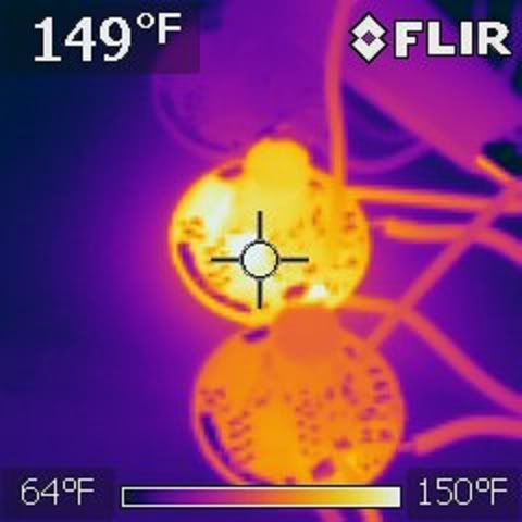
It looks like this is a bad idea. It works, but one heats up more than the other. How much more seems random. Sometimes it was 10F more, and sometimes it was 80F more. Checking anything in the circuit changes the currents (I feel like blaming Heisenberg), so I don't know why this happens for sure. I suspect one is dumping some power into the other.

IR_0081.jpg


actually there are cheaper ones that can reach 2A

With modification and additional heatsinking, yes. Are those much different than the ones I linked though?

I'll see how these cheaper ones stand up to sense-resistor swapping
 
Last edited:
It looks like this is a bad idea. It works, but one heats up more than the other. How much more seems random. Sometimes it was 10F more, and sometimes it was 80F more. Checking anything in the circuit changes the currents (I feel like blaming Heisenberg), so I don't know why this happens for sure. I suspect one is dumping some power into the other.

IR_0081.jpg


With modification and additional heatsinking, yes. Are those much different than the ones I linked though?

I'll see how these cheaper ones stand up to sense-resistor swapping

thanks for the pictures and testing. and about the drivers.
i think it gets warmer because, like i said,the voltage isn't exactly the same, the other driver will work harder( more current) and heat up. the more difference in V, the more heat.
 
Last edited:
Cyparagon said:
With modification and additional heatsinking, yes. Are those much different than the ones I linked though?

SS34 diode, don't know about the rest, the pictures are old on DX! but still cheaper :D

combining switching regulators is not that easy ...
each driver is a phase..

we have 2 phases for 2 drivers in parallel.
in reality this creates unbalance in load current sharing... just like if you are hooking up 2 or more batteries in parallel with different charge.. that way a circulating current is created between the batteries (drivers in this case) where the one is supplying current and the other is sucking..


this totally unacceptable cuz the inductors may saturate,
all the power components may overheat and the efficiency suffers greatly.

the solution to this is to provide some kind of feedback to sense the current in each of the drivers(phases) and then force them to be equal.

this can be done with error amps at the output of each driver to control the currents with control voltage to control the cycles..

but that becomes too big of a package...
 
Last edited:
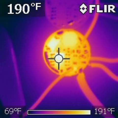
Well, I tried just jacking up the current. I used a length of Chinese wire (over there, they evidently think 34 guage is acceptable for banana plug leads) in parallel with the sense resistor and got 1.75A. I measured the efficiency at 76%, which is still substantially better than a linear driver at ~60%. The temp goes higher, but I think this is still acceptable, considering it'd be in a pointer.

This is as hot as it got, and it took about 4 minutes to get this hot:

IR_0084.jpg
 
actually there are cheaper ones :D:D:D that can reach 2A

18V 5W Cree Circuit Board for Flashlights (16.8mm*5.5mm) - Free Shipping - DealExtreme

i have tested them ;)

Hmmm so I just bought a couple of these actually. eBay - New & used electronics, cars, apparel, collectibles, sporting goods & more at low prices

I was going to use them just for battery contacts because I just got a couple of C6s from Moh's GB. I was planning on making a few different builds, but if these drivers are modified, they can be used instead of a Flexdrive for a 445, right? What kind of a modification are we looking at here? Which resistors am I replacing?

Thanks.

these are buck not boost drivers... you can use them to drive 445nm but for bigger currents like 1.5A you need 3x Li-batteries...

for current modifications you swap the resistor near the IC where the negative lead to the LD connects... the current is set by this formula I = 0.25 / R :beer:
 
Last edited:


Back
Top