rhd
0
- Joined
- Dec 7, 2010
- Messages
- 8,475
- Points
- 0
The 940nm Nightmare
There's some irony here in that I set out to showcase the universality of my MODC modules, and how awesome it is that they allow usage of a C-Mount diode in traditional 12mm heatsinks.... but then I went off and built the MODC into a non-traditional heatsink. For those just jumping, here's a discussion of the MODC: http://laserpointerforums.com/f40/modc-experimenting-c-mount-builds-3w-ir-progress-89056.html
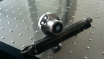
Some people have asked how the diode is fixed to the MODC. It doesn't require thermal epoxy, and in fact as much of a fan of thermal epoxy as I am, I'm not using it here. Regular thermal compound is perfect, because the copper backing screws down tight and holds the diode secure (and adds to the heatsinking). Using thermal compound instead of epoxy means you can remove the diode if need be. Here's what it looks like:

Here are the specs of the build:
- For a diode, I decided to use a 4W 940nm C-Mount.
- For optics, I'm using a typical G9 lens (thanks to the MODC)
- For a driver, I'm using a version of my 5A buck driver. I haven't named it, but to keep the revisions straight, my internal version/code name is 5AB22V04.
- For power, the build uses 2x 250mAh high drain LiPo cells.
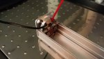
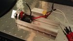
The driver isn't tiny. I haven't done much working trying to miniaturize it, and you'll notice that the surface mount inductor pushes the limits of the term "surface mount" - it's pretty big. But the driver has been working well, and has no issue running from the VINs I've tested all the way up to 16V. For this build, the driver is only seeing an input of 7.4V (nominal) from the 2x LiPo cells.

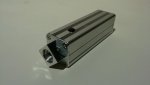
Here's the finished product. I know the black clicky isn't the classiest option, but for this build, I actually wanted a less pronounced button that would be somewhat recessed and more difficult to press.

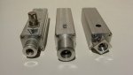
Here's the build next to some of it's kin. On the far left, you'll see the Ninja MKII (which was showcased here). In the middle, you'll see the NINJA MKIII, which was never showcased, but is the cooler of the two in that it has built in tactile feedback (which you can here, slightly, in the video that follows). On the right, is the 940nm Nightmare.

Now, before I get to showcasing the build video video, it's worth talking about this wavelength. 940nm is IR, but it's a whole different beast from the 808nm we're more familiar with. At 808nm, must people can still perceive a faint red tint. At 940nm, you see absolutely nothing at all, not the faintest hint of anything, whatsoever. In fact, the old trick of using a webcam/digital camera to pick up the spot *barely* works. My cell phone picks up the wavelength, but it's fairly dim even then, and I have a couple other cameras that don't see it at all. This creates a very unique challenge when trying to focus the laser, and needless to say, introduces a need for very careful and cautious usage. In the video below, you'll notice that it I initially have some difficulty training its output on the LPM sensor.
Safety glasses (rated for 940nm) were worn in these videos.
A comparison of 2 blue NINJA builds (MKII and MKIII) to the 940nm Nightmare
https://www.youtube.com/watch?v=PLiYi3lR384&feature=youtu.be
And a black tape video.
https://www.youtube.com/watch?v=5zT3RqtcC7Y&feature=youtu.be
There's some irony here in that I set out to showcase the universality of my MODC modules, and how awesome it is that they allow usage of a C-Mount diode in traditional 12mm heatsinks.... but then I went off and built the MODC into a non-traditional heatsink. For those just jumping, here's a discussion of the MODC: http://laserpointerforums.com/f40/modc-experimenting-c-mount-builds-3w-ir-progress-89056.html
Some people have asked how the diode is fixed to the MODC. It doesn't require thermal epoxy, and in fact as much of a fan of thermal epoxy as I am, I'm not using it here. Regular thermal compound is perfect, because the copper backing screws down tight and holds the diode secure (and adds to the heatsinking). Using thermal compound instead of epoxy means you can remove the diode if need be. Here's what it looks like:
Here are the specs of the build:
- For a diode, I decided to use a 4W 940nm C-Mount.
- For optics, I'm using a typical G9 lens (thanks to the MODC)
- For a driver, I'm using a version of my 5A buck driver. I haven't named it, but to keep the revisions straight, my internal version/code name is 5AB22V04.
- For power, the build uses 2x 250mAh high drain LiPo cells.
The driver isn't tiny. I haven't done much working trying to miniaturize it, and you'll notice that the surface mount inductor pushes the limits of the term "surface mount" - it's pretty big. But the driver has been working well, and has no issue running from the VINs I've tested all the way up to 16V. For this build, the driver is only seeing an input of 7.4V (nominal) from the 2x LiPo cells.
Here's the finished product. I know the black clicky isn't the classiest option, but for this build, I actually wanted a less pronounced button that would be somewhat recessed and more difficult to press.
Here's the build next to some of it's kin. On the far left, you'll see the Ninja MKII (which was showcased here). In the middle, you'll see the NINJA MKIII, which was never showcased, but is the cooler of the two in that it has built in tactile feedback (which you can here, slightly, in the video that follows). On the right, is the 940nm Nightmare.
Now, before I get to showcasing the build video video, it's worth talking about this wavelength. 940nm is IR, but it's a whole different beast from the 808nm we're more familiar with. At 808nm, must people can still perceive a faint red tint. At 940nm, you see absolutely nothing at all, not the faintest hint of anything, whatsoever. In fact, the old trick of using a webcam/digital camera to pick up the spot *barely* works. My cell phone picks up the wavelength, but it's fairly dim even then, and I have a couple other cameras that don't see it at all. This creates a very unique challenge when trying to focus the laser, and needless to say, introduces a need for very careful and cautious usage. In the video below, you'll notice that it I initially have some difficulty training its output on the LPM sensor.
Safety glasses (rated for 940nm) were worn in these videos.
A comparison of 2 blue NINJA builds (MKII and MKIII) to the 940nm Nightmare
https://www.youtube.com/watch?v=PLiYi3lR384&feature=youtu.be
And a black tape video.
https://www.youtube.com/watch?v=5zT3RqtcC7Y&feature=youtu.be


")