Welcome to Laser Pointer Forums - discuss green laser pointers, blue laser pointers, and all types of lasers

LPF Donation via Stripe | LPF Donation - Other Methods

Links below open in new window

ArcticMyst Security by Avery

Test Load Verification

Joined
Jun 24, 2009
Messages
88
Points
0
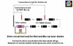
I have recently finished my laser test load for red lasers.

I just wanted to verify that I build it correctly.

The top side: 4 1N40001 diodes in a line on a breadboard, then 1 lead from the last diode to a 10 ohm resistor.I have leads from the resistor and from the diodes to connect them to the driver.

The bottom side: The pins of diodes that are next to each other are soldered together.Thats it.

I really want to know if this will work.I will post a youtube video about it when I get back from vacation.

Thanks,
Logan


Joined
May 4, 2009
Messages
2,237
Points
83
Umm.... i believe you are suppose to use a 1 ohm resistor, at least that what i have on mine and from what i remember reading when i built it sometime ago.

A quick check, and yes, its a 1 ohm resistor. Lasersbee has a tread where hes giving away 1 ohm 1/2W resistors for the price of shipping. The test load for reds should be four diodes and the resistor all in parallel, and the current measurment taken across the resistor

I've attached a photo of what it should look like. This photo is property of ROG8811, i may no claim that is mine( i'd be rather foolish to do so as his name is in the pic) :D
 

Attachments

  • test%20load01.jpg
    test%20load01.jpg
    41.2 KB · Views: 886
Joined
Dec 23, 2008
Messages
3,948
Points
63
gryphon is correct. it is a 1 ohm resistor. i don't use a bread board. i just solder end to end and bend into a U. the striped end of the diode will connect to the resistor and the resistor goes to the negative output of the test load. and the other end of the dummy load to the positive output.
 
Joined
Mar 20, 2008
Messages
1,341
Points
0
Is it possible to use any diodes as long as the correct voltage drop is achieved?
 
Joined
Jul 1, 2009
Messages
588
Points
18
The top side: 4 1N40001 diodes in a line on a breadboard, then 1 lead from the last diode to a 10 ohm resistor.I have leads from the resistor and from the diodes to connect them to the driver.

i think is ok to use 10ohm resistor but with 10ohm resistor when you read the current to the DMM 1mv equals with 10mA.
 
Joined
Mar 8, 2009
Messages
710
Points
0
The problem is, your voltage drop will be 10x as great as with a 1 Ohm resistor. This means, using the standard 4x1N400x for red and 6x1N400x for BR, you wouldn't be able to set the usual currents of 420mA for an LPC or 120mA for a PHR diode using a FlexDrive, as the output voltage would have to be at or above 6V.

Oh btw, it's the other way round: 10mV would mean 1mA.
 

lmn

0
Joined
May 14, 2009
Messages
44
Points
0
Umm.... i believe you are suppose to use a 1 ohm resistor, at least that what i have on mine and from what i remember reading when i built it sometime ago.

A quick check, and yes, its a 1 ohm resistor. Lasersbee has a tread where hes giving away 1 ohm 1/2W resistors for the price of shipping. The test load for reds should be four diodes and the resistor all in parallel, and the current measurment taken across the resistor

I've attached a photo of what it should look like. This photo is property of ROG8811, i may no claim that is mine( i'd be rather foolish to do so as his name is in the pic) :D

Isn't it in series, not parallel?

That's what the image shows
22788d1249505515-test-load-verification-test-20load01.jpg


Top