Welcome to Laser Pointer Forums - discuss green laser pointers, blue laser pointers, and all types of lasers

LPF Donation via Stripe | LPF Donation - Other Methods

Links below open in new window

ArcticMyst Security by Avery

Starting a 2 Mirror setup project

Joined
Sep 12, 2007
Messages
207
Points
0
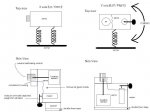
Ok so I had a few questions about this type of project. I have a good understand of the parts needed and have most of them laying around. The only big question I have right now is about the mounting of the mirrors on the spinning motors. I thought I read somewhere, but can't find it now, that the mirrors need to be mounted so they "wobble" alittle and don't spin perfectly flat. Granted when I think about it, it sort of makes sense but I'd rather have someone that has built one of these tell me I'm right before I go Superglueing mirrors around.

And if I am right some tips on how to mount it off axis would be awesome.

Thanks guys.


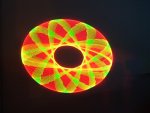
P.S I'll be making a unit that will take any laser input as the unit itself will nto have a built in laser unit. I'll explain more as I move forward.


Amnizu

0
Joined
Jan 15, 2008
Messages
607
Points
0
A friend of mine used Gorilla glue, which expands 3-4x when it dries, so the glue itself provided the slight angle needed for his time tunnel. Maybe you could go to Target and pick some up for $5. If you have Targets where you live, anyway.
 
Joined
Jan 12, 2008
Messages
3,290
Points
83
Here's what I do:

1 Cut a 5-10mm long pice of hotglue stick. Depending on how long the drive shafts are, the longer the better.
2 Put a few drops of melted hotglue on the back and in the center of the mirror.
3 Attach the 5-10mm hotglue stick.
4 Make a small hole in the center of the 5-10mm glue stick with a nail. Make sure that the nail is not bigger than the drive shaft. A pin does also work.
5 Attach the motor drive shaft in the hole.
6 Done  :).

Another way is to use something like a eraser and superglue.
If the angle is too small or too big, you can try to bend it or make a new hole. Different angles makes different patterns, adjust to your likeing.  ::)
 
Joined
Sep 12, 2007
Messages
207
Points
0
Thanks i'll give it a shot tonight. if I get it working i'll post some shots of it with my DIY red. (still waiting on my green from DrLava.... I can almost taste it.... it burns)


Does anyone have a preference or is there a difference between using 2 or 3 mirriors? I've seen both setups.

and I assume it's better to have both Motors be adjustable instead of just one, yes?
 
Joined
Jan 12, 2008
Messages
3,290
Points
83
Make both adjustable (if you're talking about speed) and make it possible to change the direction on one (or both) of the motors.
In that way can you get allot of patterns  ;). Three mirrors makes more complicated patterns and is quite fun  :D.
 
Joined
Sep 12, 2007
Messages
207
Points
0
ok for the mirrors glued up, they work perfectly.

so now I just need to get a box I like after work and some other pieces here and there and I should have it all together tonight.
 
Joined
Dec 26, 2007
Messages
6,129
Points
0
i have redone some parts of my spirograph, i will post pictures when i finish it...(been working on it for the past 2 days...still working on it :p)
 

Things

0
Joined
May 1, 2007
Messages
7,517
Points
0
Just a hint, you do not need to worry about the tilted mirrors. as long as you just dont pay attention to how flat you make them, you are garanteed to get them slightly off angle. Just find a secure way to mount the mirrors to the motor shafts and your fine. As for control, make both motors controllable, it will enable you to create more patterns.
 
Joined
Jan 12, 2008
Messages
3,290
Points
83
Oh, I forgot to tell what switch that you need to change the direction and how to wire it up.
You need a two polarity on-off-on switch with six pins. I numbered the pinns seen form the bottom.

1 2 3
o o o

o o o
4 5 6

Connect pin 1 to pin 6
Connect pin 4 to pin 3
Connect pin 2 and pin 5 to the power. You don't need to think about the polarity.
Connect pin 3 and pin 6 to the motor. Or pin 1 and pin 4, it doesn't matter.
Hope that helps.
 

Ace82

0
Joined
Feb 11, 2008
Messages
1,768
Points
0
Hehe, I'm working on one right now that uses my old RC heli 6ch transmitter and receiver (although I’m only using 2).  You can either control X & Y concurrently by the stick manually, or using the trim.  All I do is I disconnect the location control from gears of the two servos to where I can control it manually (as to calibrate it's neutral position).  I use double foam tape to mount the motors to a stand and two springs each connecting to the mirror.  
 

Attachments

  • servos_001.JPG
    servos_001.JPG
    63.6 KB · Views: 112
Joined
Sep 12, 2007
Messages
207
Points
0
I was thinking of getting a cheap RC car and gutting it for the board and making an XY scanner that was wirelessly controlled actually.

Once I get this done first i'll consider that my next project.
 
Joined
Jul 27, 2007
Messages
3,642
Points
63
FireMyLaser said:
Haha, that is awesome! Does it look like that in real life?

it would if i used faster motors, i have it on slow pc fans atm so it appears to the eye as a circle, but after a 6 second exposure it looks awesome
 
Joined
Sep 26, 2007
Messages
54
Points
0
ok now you guys have done it, i have to build one,.. one color or two..

how many MW laser do you generally use for them? I might make one with either R/G or both :)

Do PC fans spin fast enough? or is the something more preferable for a motor?
One lase Q, for working with laser i know you should have goggles but for making designs.. you dont need them to view them. they are scanning fast enough to be safe?


Top